
Transflective liquid crystal display panel and liquid crystal display

A liquid crystal display panel, transflective technology, applied in instruments, nonlinear optics, optics, etc., can solve the cumbersome manufacturing process of the transflective liquid crystal display panel and increase the preparation process of the transflective liquid crystal display panel Difficulty and other issues to achieve the effect of reducing the difficulty of the preparation process and simplifying the preparation process

Inactive Publication Date: 2014-12-10
BOE TECH GRP CO LTD +1
View PDF6 Cites 26 Cited by
  • Summary
  • Abstract
  • Description
  • Claims
  • Application Information

AI Technical Summary

Problems solved by technology

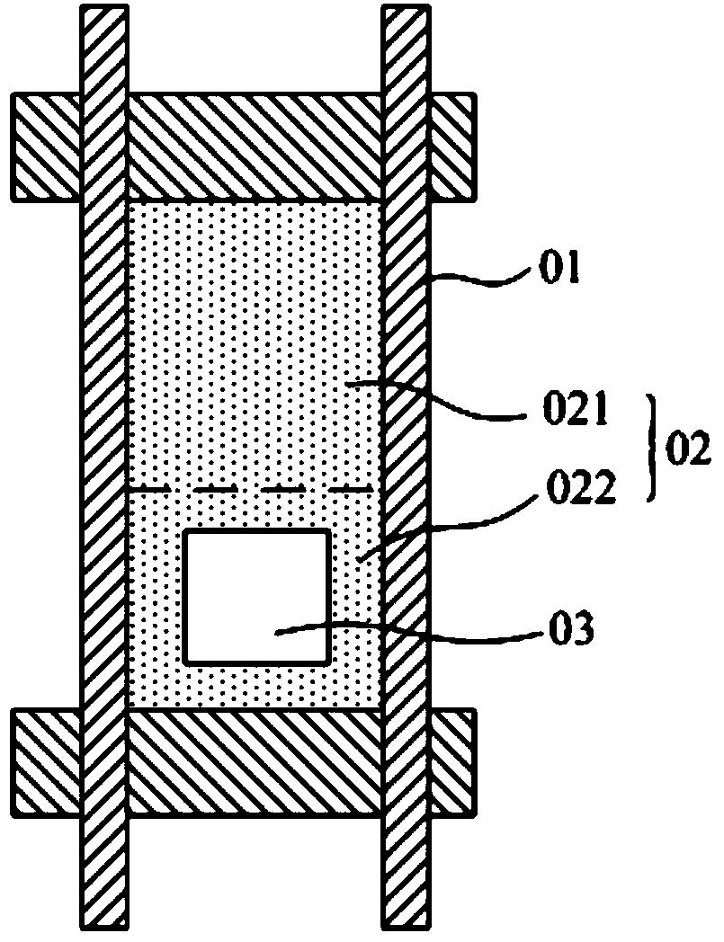
[0005] However, in the prior art, an opening 03 is set on the color filter layer through a mask exposure process, and a transparent filter is filled in the opening 03, so that the manufacturing process of the transflective liquid crystal display panel is relatively cumbersome and increases half Difficulty in manufacturing process of transflective liquid crystal display panel

Method used


Image

  • Transflective liquid crystal display panel and liquid crystal display
  • Transflective liquid crystal display panel and liquid crystal display
  • Transflective liquid crystal display panel and liquid crystal display

Examples


Embodiment 1

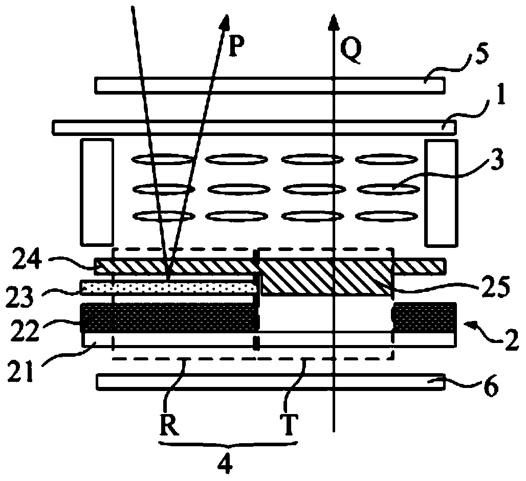
[0028] Please refer to figure 2 , the transflective liquid crystal display panel provided in this embodiment includes an upper substrate 1 and a lower substrate 2 connected to the cell, and a liquid crystal layer 3 filled between the upper substrate 1 and the lower substrate 2; wherein, the lower substrate 2 It includes a plurality of sub-pixel units 4 distributed in an array, and each sub-pixel unit 4 includes a reflective region R and a transmissive region T. Along the direction from the lower substrate 2 to the upper substrate 1, the reflective region R sequentially includes a base substrate 21 and a black matrix 22 , the reflective layer 23 and the first color filter layer 24, the transmissive region T includes the base substrate 21 and the second color filter layer 25 in sequence, and the thickness of the first color filter layer 24 is smaller than that of the second color filter layer 25 thickness. Wherein, the first color filter layer 24 and the second color filter la...

Embodiment 2

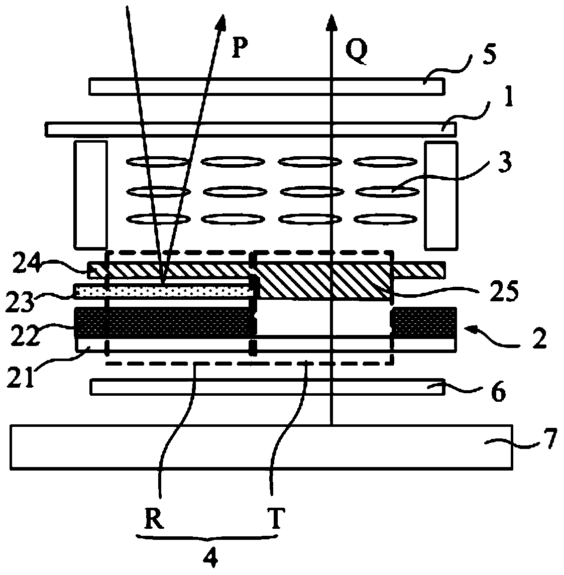
[0041] Please refer to image 3 , this embodiment provides a transflective liquid crystal display, including a backlight source 7 and the transflective liquid crystal display panel provided in the first embodiment above, wherein the backlight source 7 is located in the liquid crystal display panel and the lower substrate 2 is away from One side of the upper substrate 1.

[0042] In the transflective liquid crystal display panel provided by the first embodiment above, there is no need to set openings and transparent filters in the reflective region R of each sub-pixel unit 4, so that the color saturation of the reflective region R and the transmissive region can be improved. The color saturation of T tends to be consistent, so that the preparation process of the transflective liquid crystal display panel omits the process of setting openings and transparent filters in the reflection region R of the sub-pixel unit 4. Therefore, in the transflective liquid crystal display with t...


PUM


Abstract

The invention discloses a transflective liquid crystal display panel and a liquid crystal display. The transflective liquid crystal display panel comprises an upper base plate, a lower base plate and a liquid crystal layer, wherein the upper base plate and the lower base plate are in butt joint, and the liquid crystal layer is arranged between the upper base plate and the lower base plate. The lower base plate comprises a plurality of sub-pixel units distributed in arrays, wherein each sub-pixel unit comprises a reflection area and a transmission area, the reflection area sequentially comprises a substrate base plate, a black matrix, a reflection layer and a first color filter layer in the direction from the lower base plate to the upper base plate, the transmission area sequentially comprises a substrate base plate and a second color filter layer in the direction from the lower base plate to the upper base plate, and the thickness of the first color filter layer is smaller than that of the second color filter layer. By means of the transflective liquid crystal display panel, it is ensured that difficulty in the preparation technology of the transflective liquid crystal display panel can be reduced under the conditions that color saturation of the reflection areas and color saturation of the transmission areas trend to consistence.

Description

technical field [0001] The invention relates to the technical field of liquid crystal display, in particular to a transflective liquid crystal display panel and a liquid crystal display. Background technique [0002] Currently, a liquid crystal display (LCD) is one of the most widely used flat panel displays. According to the light source used by the liquid crystal display, the liquid crystal display is classified as a transmissive liquid crystal display or a reflective liquid crystal display. The transmissive liquid crystal display uses backlight as the light source, and the light emitted by the light source passes through the liquid crystal display panel and enters the human eye to display images; in this type of liquid crystal display, a backlight generator is installed behind the liquid crystal display panel, which can display Produces images with high contrast and good color saturation. However, when the intensity of external light is greater than the intensity of lig...

Claims


Application Information

Patent Timeline
Patent Type & Authority Applications(China)
IPC IPC(8): G02F1/1335
Inventor 冯远明
Owner BOE TECH GRP CO LTD
Learn More