Supercharge Your Innovation With Domain-Expert AI Agents!

A liquid-cooled heat dissipation structure for an ultrasonic motor

An ultrasonic motor, liquid-cooled heat dissipation technology, applied in the direction of generator/motor, piezoelectric effect/electrostrictive or magnetostrictive motor, electrical components, etc. Complex problems, to achieve the effect of improving heat dissipation efficiency and working stability, increasing cooling effect, and promoting popularization and application

Active Publication Date: 2017-01-25
SHANGHAI JIAOTONG UNIV
View PDF7 Cites 0 Cited by
  • Summary
  • Abstract
  • Description
  • Claims
  • Application Information

AI Technical Summary

Problems solved by technology

[0006] However, those skilled in the art know that the heat dissipation efficiency of the ultrasonic motor is limited by the air-cooled heat dissipation method in the prior art, because the ultrasonic motor works at a low speed , cannot rely on its own rotation to provide cooling air, and the ultrasonic motor itself is generally used in the integrated application of micro-electromechanical systems, which has strict restrictions on the installation size, and the installation of air-cooled blades for heat dissipation on the motor shell will inevitably increase the volume of the motor; therefore , the traditional air-cooled technology is not suitable for the promotion and application of ultrasonic motors
[0007] In addition: the cooling system in the Chinese Patent Publication No. CN 102664477A requires an external drive motor to drive the refrigeration system. The effect is difficult to guarantee, and the processing cost is high and the process is complicated. Therefore, it is not conducive to the popularization and application of ultrasonic motors.

Method used


Image

  • A liquid-cooled heat dissipation structure for an ultrasonic motor
  • A liquid-cooled heat dissipation structure for an ultrasonic motor

Examples


Embodiment

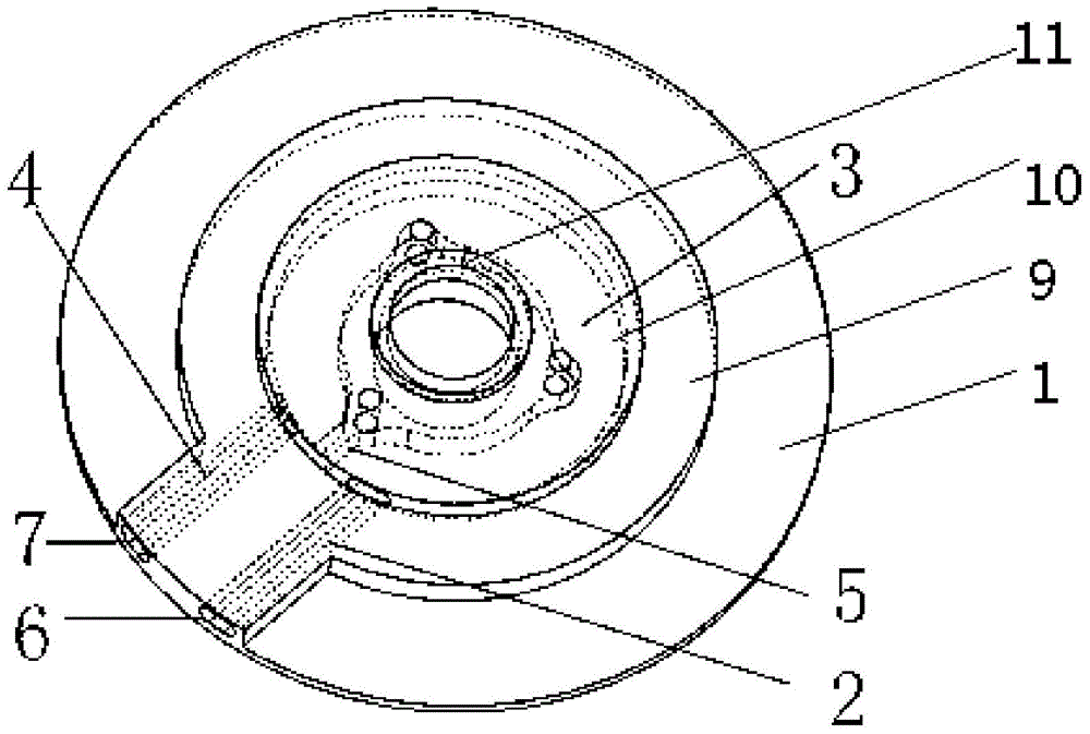
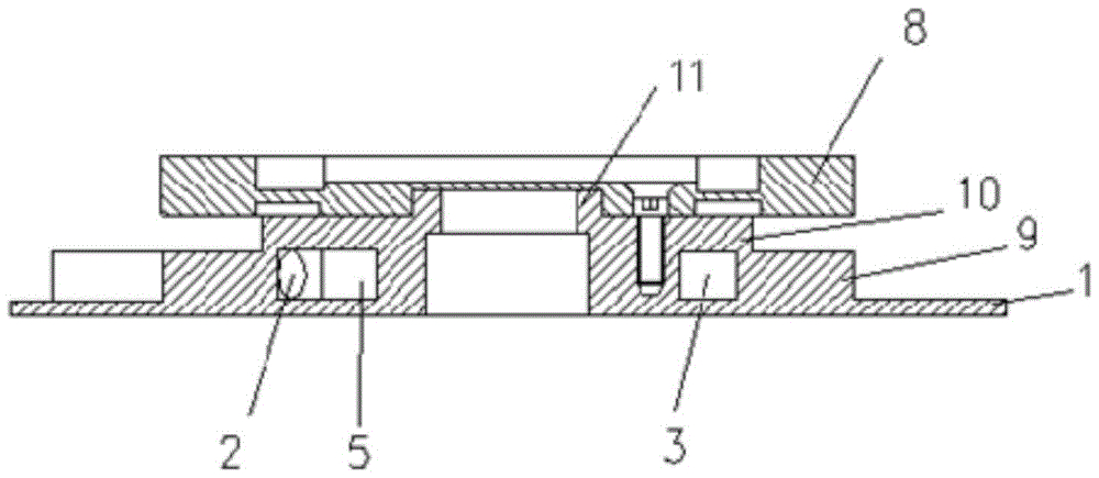
[0028] Such as Figure 1 to Figure 2 as shown, figure 1 It is a perspective view of the cooling base of the heat dissipation structure of the ultrasonic motor of the present invention; figure 2 It is a schematic cross-sectional view of the cooling base of the ultrasonic motor heat dissipation structure and the stator assembly of the ultrasonic motor in the present invention; figure 1 and figure 2 A cooling base of a liquid-cooled heat dissipation structure of an ultrasonic motor and its installation diagram are illustrated, including a cooling base fixedly connected to a stator 8 of an ultrasonic motor, and a cooling inlet channel 2 and a cooling ring are arranged in the cooling base in sequence. Flow channel 3 and cooling outlet channel 4, the opening of the cooling inlet channel 2 on the side wall of the cooling base is a cooling liquid inlet 6, and the cooling outlet channel 4 is on the side wall of the cooling base The opening of the cooling liquid outlet 7; the cooli...


PUM


Abstract

The invention discloses a liquid-cooling heat dissipation structure for an ultrasonic motor. According to the liquid-cooling heat dissipation structure, the stator of the ultrasonic motor is fixed and cooled through a cooling base internally provided with a cooling flow passage, a cooling liquid inlet and a cooling liquid outlet are formed in the cooling base, the cooling liquid enters to the cooling base from the cooling liquid inlet, passes through a cooling inlet flow passage, a cooling annular flow passage and a cooling outlet flow passage, and then flows out from the cooling liquid outlet; the cooling base is configured to be a hollow structure, and the forced convection action of the cooling liquid enables the cooling base to be provided with an extremely high thermal convection coefficient, thus greatly improving the cooling effect of the motor, and then greatly reducing the working temperature rise of the motor. The liquid-cooling heat dissipation structure disclosed by the invention is simple and compact in structure, convenient to install and use, and capable of improving the heat dissipation efficiency and working stability of the ultrasonic motor, thus promoting the popularization and application of the ultrasonic motor.

Description

technical field [0001] The invention relates to the technical field of ultrasonic motor applications, in particular to the technical field of a cooling structure for an ultrasonic motor. Background technique [0002] At present, ultrasonic motors are more and more widely used. In the traditional design, the stator of the ultrasonic motor is fixed on the aluminum motor base, and the entire stator and rotor structure is placed in a relatively closed motor housing; the heat generated in the stator is conducted through contact. to the base of the motor, and then diffused to the outside air from the motor casing. [0003] However, the common heat dissipation method of the ultrasonic motor has the following problems in use, because the ultrasonic motor generates heat seriously during operation, and it will cause a high temperature rise of the stator under continuous operating conditions, which will cause changes in the characteristics of the ultrasonic motor, such as The drift of...

Claims


Application Information

Patent Timeline
Patent Type & Authority Patents(China)
IPC IPC(8): H02N2/12H02N2/00
Inventor 杨明欧文初孟凡李奇磊许自豪
Owner SHANGHAI JIAOTONG UNIV
Features
  • R&D
  • Intellectual Property
  • Life Sciences
  • Materials
  • Tech Scout
  • Unparalleled Data Quality
  • Higher Quality Content
  • 60% Fewer Hallucinations
Learn More