
Miniature impact piezoelectric-drive rotary joint and method for controlling same

A technology of piezoelectric drive and rotary joints, applied in the direction of piezoelectric effect/electrostrictive or magnetostrictive motors, generators/motors, electrical components, etc., can solve the problem of low miniaturization, low efficiency, and driving force Insufficient and other problems, to achieve the effect of simple driving mode, stable structure and optimized layout

Inactive Publication Date: 2014-12-10
HEFEI UNIV OF TECH
View PDF5 Cites 5 Cited by
  • Summary
  • Abstract
  • Description
  • Claims
  • Application Information

AI Technical Summary

Problems solved by technology

[0005] The purpose of the present invention is to overcome the technical problems of low miniaturization, insufficient driving force and low efficiency of the existing impact piezoelectric rotary motors, and provide a miniaturized impact piezoelectric drive rotary joint suitable for micro precision operators and its Control method to improve operating efficiency and stability, and reduce the complexity of the drive circuit for easy control

Method used


Image

  • Miniature impact piezoelectric-drive rotary joint and method for controlling same
  • Miniature impact piezoelectric-drive rotary joint and method for controlling same
  • Miniature impact piezoelectric-drive rotary joint and method for controlling same

Examples


Embodiment Construction

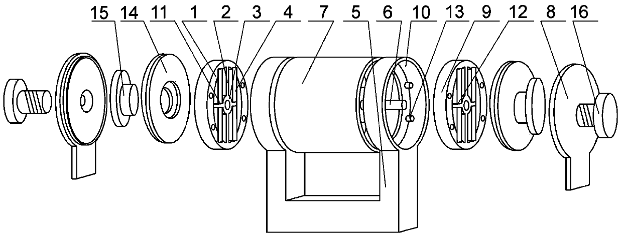
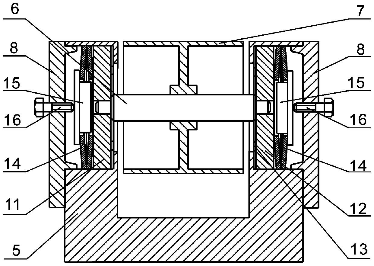
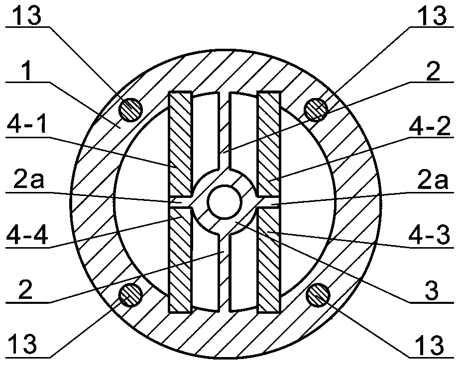
[0027] see figure 1 , figure 2 , image 3 and Figure 4 In this embodiment, the micro-impact piezoelectric-driven rotary joint includes a U-shaped base 5, and a rotating sleeve 7 horizontally clamped in the U-shaped opening on the U-shaped base 5, and the central axis of the rotating sleeve 7 rotates The rotating shaft 6 is installed, and the two ends of the U shape on the U-shaped base 5 are respectively connected with annular seats 10, and the two annular seats 10 are connected to the two ends of the rotating sleeve 7 corresponding to the central axis respectively. Ring-shaped bearing housings 1 are respectively installed in the bearing housing 1. The inner ring wall of the bearing housing 1 is connected with a bearing frame 2 along a certain radial direction. The bearing frame 2 is disconnected at the middle position and connected with a bearing ring 3 in a complete ring. 3 and the bearing seat 1 are the same circle center, on the outer circumferential surface of the be...


PUM


Abstract

The invention discloses a miniature impact piezoelectric-drive rotary joint which is characterized by comprising a U-shaped base. A rotary sleeve is horizontally clamped by the U-shaped base, and a rotary shaft is rotationally mounted at the central axis of the rotary sleeve. The miniature impact piezoelectric-drive rotary joint has the advantages that bearing driving modules comprise bearing units and piezoelectric ceramic plates, and preset clamping force is exerted to the rotary shaft by bearing rings; time sequences of synchronous zigzag rotation of the bearing driving modules at two ends of the miniature impact piezoelectric-drive rotary joint are controlled, the rotary shaft can move in a stepping manner under an inertial impact effect, accordingly, the running efficiency and stability can be effectively improved, layout of the piezoelectric ceramic plates can be optimized, the complexity of driving circuits can be lowered, and the miniature impact piezoelectric-drive rotary joint is convenient to control.

Description

technical field [0001] The invention relates to the field of drivers, and mainly relates to a miniature impact piezoelectric driven rotary joint. The invention belongs to the technical field of micro-nano operation in precision machinery, and relates to a piezoelectric motor mechanism for realizing the stepping and rotating motion of a micro-operating hand joint by using the impact principle, in particular to the piezoelectric-driven rotary joint mechanism and its control method. Background technique [0002] In precision positioning drive systems, the drive has a decisive influence on the performance of the entire system. The size of the traditional mechanical drive structure is large, the precision is not high, it is difficult to achieve the positioning accuracy of the micro-nano level, and it cannot meet the needs of the micro-nano-level positioning accuracy in many frontier fields. Therefore, the development of new drivers has become one of the key links in the developm...

Claims


Application Information

Patent Timeline
Patent Type & Authority Applications(China)
IPC IPC(8): H02N2/12H02N2/14
Inventor 潘成亮韩丽玲于连栋李维诗张进夏豪杰赵会宁陆洋
Owner HEFEI UNIV OF TECH
Learn More