Main drive gear of numerical control right-angle plate shearing machine

A shearing machine and main drive technology, applied in shearing machine equipment, shearing device, metal processing equipment and other directions, can solve the problems of difficult to ensure accuracy, slow adjustment speed, environmental pollution, etc., to achieve compact device structure, reduce Energy consumption, the effect of eliminating the cooling system

Active Publication Date: 2011-08-17
JIANGSU JINFANGYUAN CNC MACHINE CO LTD
View PDF7 Cites 3 Cited by
  • Summary
  • Abstract
  • Description
  • Claims
  • Application Information

AI Technical Summary

Problems solved by technology

Its disadvantages are: the device needs to be equipped with a hydraulic oil cooling system, and the leakage of hydraulic oil and the treatment of waste oil will cause certain environmental pollution. In addition, when working, the oil pump in the hydraulic pump station is continuously working, which will generate a lot of Heat energy loss, the shearing machine also consumes electricity when it is not cutting, which is not conducive to energy saving
Its shortcoming is: in this device, the motor is always working, which causes the problem of high energy consumption
In addition, the shearing stroke of the existing right-angle shearing machine needs to be adjusted on site. The adjustment method is mechanical adjustment, the adjustment speed is slow, and the accuracy is not easy to be guaranteed.

Method used


Image

  • Main drive gear of numerical control right-angle plate shearing machine
  • Main drive gear of numerical control right-angle plate shearing machine
  • Main drive gear of numerical control right-angle plate shearing machine

Examples


Embodiment Construction

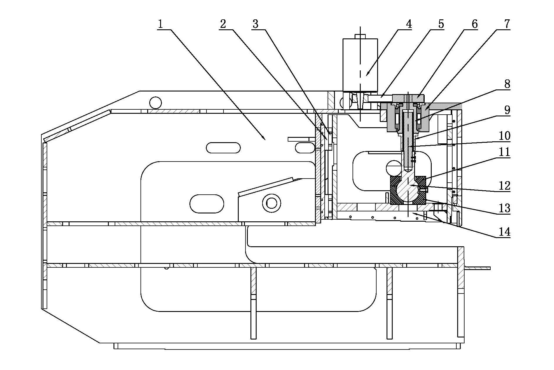
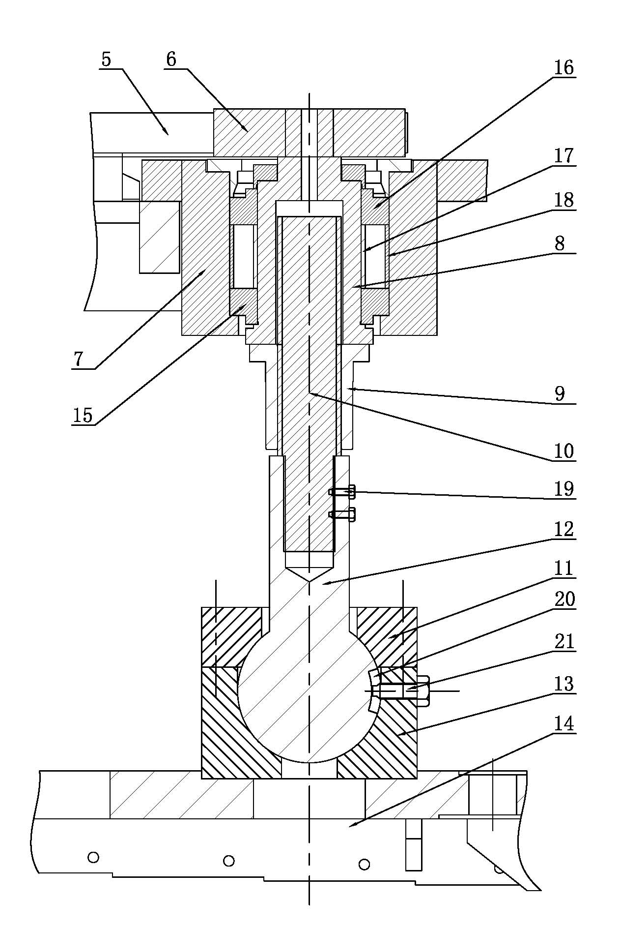
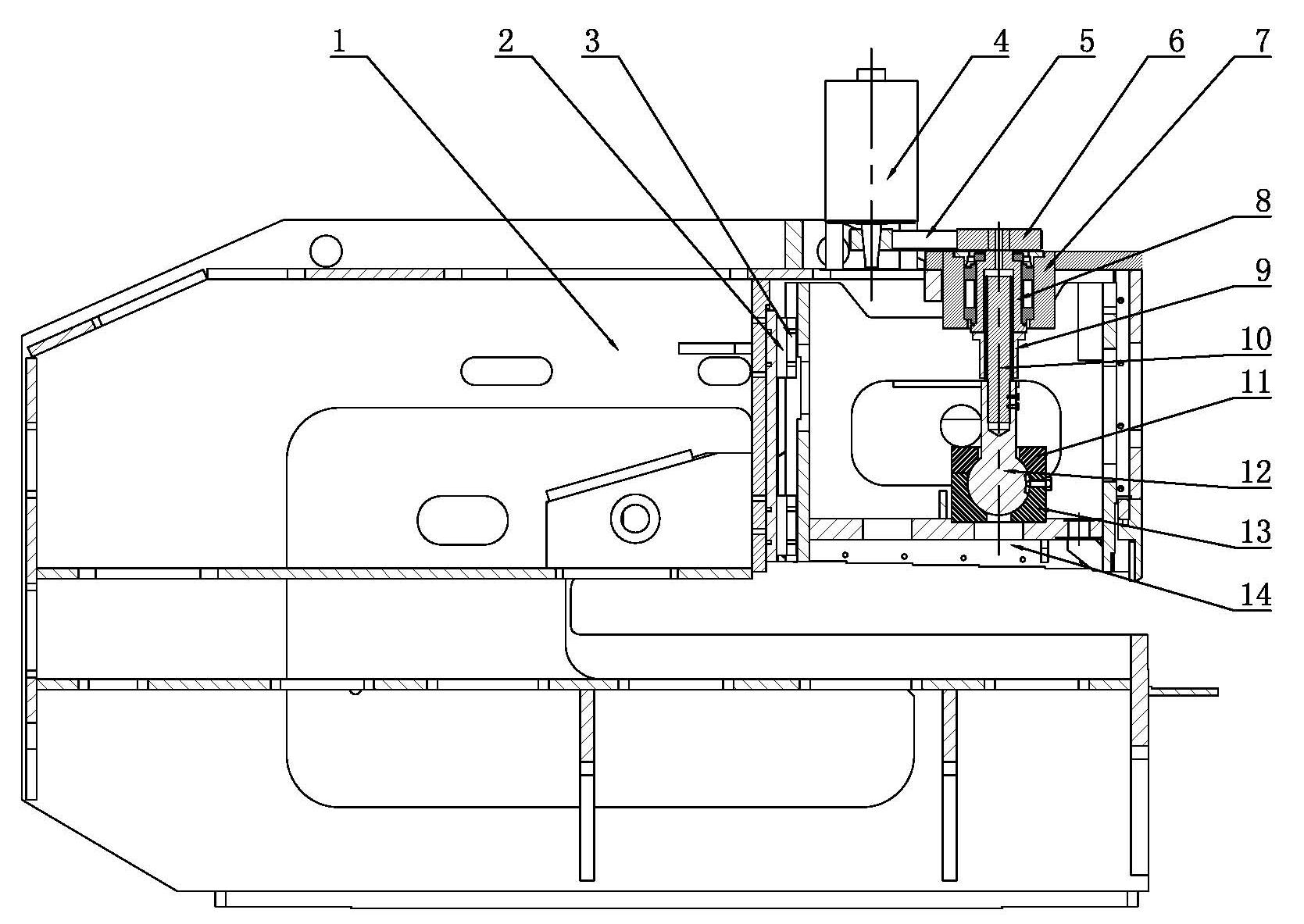
[0015] Such as figure 1 with 2 As shown, it is the main transmission mechanism of the CNC right-angle shearing machine, which mainly includes a fuselage 1. The guide rail slider mechanism set upright on the fuselage 1 is connected with the upper tool rest 14. The guide rail slider mechanism is composed of mutually matched guide rails 2 and The slider 3 is composed of the guide rail 2 fixed on the fuselage 1, the slider 3 is fixed with the upper tool holder 14; the servo motor 4 and the bearing seat 7 are installed on the fuselage 1, and the output shaft of the servo motor 4 passes through the timing belt 5 and The synchronous pulley 6 is connected to the upper end of the hollow support shaft 8, the support shaft 8 is installed on the bearing seat 7 through the upper bearing 16 and the lower bearing 15, and an inner spacer 17 and an outer spacer are arranged between the upper bearing 16 and the lower bearing 15 18. The support shaft 8 is connected with the ball screw kinematic...


PUM


Abstract

The invention discloses a main drive gear of a numerical control right-angle plate shearing machine in the field of plate shearing machine, which comprises a machine body; an upper knife rest is connected with the machine body through an uprightly arranged guide rail sliding block mechanism; a servo motor and a bearing pedestal are arranged on the machine body; an output shaft of the servo motor is connected with the upper end of a hollow support shaft through a synchronous belt and a synchronous belt wheel; the support shaft is mounted on the bearing pedestal through a bearing; the support shaft is connected with a ball-screw kinematic pair; a nut in the ball-screw kinematic pair is fixed at the lower end of the support shaft; the upper end of a screw rod in the ball-screw kinematic pair stretches into the hollow support shaft; the lower end of the screw rod in the ball-screw kinematic pair is fixedly connected with the shaft end of a ball rod; the ball part at the lower end of the ball rod is correspondingly arranged in a ball seat; a ball gland bush for fixing the ball rod is connected with the ball seat; and the ball seat is fixedly connected with the upper knife rest. The main drive gear of the numerical control right-angle plate shearing machine has the advantages of energy saving, quick processing, and high processing precision, and can be used for the right-angle shearing processing of various plate materials.

Description

technical field [0001] The invention relates to a shearing machine tool, in particular to a shearing machine tool for cutting out two right-angled sides on a plate. Background technique [0002] In the prior art, the right-angle shearing machine cuts out two sides perpendicular to each other on the sheet through two blades arranged perpendicular to each other in one cut, and the processing speed is fast and the efficiency is high. [0003] There are two main types of existing right-angle shears: one is a pendulum shear, such as a pendulum right-angle shear disclosed in ZL200720044742. , lower main blade, upper side blade, lower side blade, gap adjustment device, hydraulic system, and electrical system. The upper main blade and upper side blade are installed on the tool holder. The upper main blade and the upper side blade are perpendicular to each other. There are lower main blades and lower side blades, the lower main blades and the lower side blades are perpendicular to e...

Claims


Application Information

Patent Timeline
IPC IPC(8): B23D15/12B23D15/06
Inventor 曹培东
Owner JIANGSU JINFANGYUAN CNC MACHINE CO LTD
Why Eureka
Try Eureka