LED lamp band

A technology for LED strips and lamp beads, which is applied to the loss prevention measures of lighting devices, lighting and heating equipment, semiconductor devices of light-emitting elements, etc., can solve the problems of complex production process, many production steps, and difficult processing, etc. Fewer production processes, precise line layout, and reduced labor intensity

Pending Publication Date: 2018-07-20
杭州小太阳农业科技有限公司
View PDF9 Cites 2 Cited by
  • Summary
  • Abstract
  • Description
  • Claims
  • Application Information

AI Technical Summary

Problems solved by technology

[0002] LED light strips are more and more widely used in the decorative lighting market due to their long service life, energy saving and environmental protection. The current LED flexible light strips are usually composed of lamp beads and flexible printed circuit boards (FPC for short). However, in the production process of flexible circuit boards, various heavy metals and organic wastewater are discharged, the composition is complex, and the treatment is difficult. If the metals in the waste liquid and wastewater are discharged without treatment, it will cause waste. polluted the environment
And the production of flexible circuit boards (single-sided system) mainly includes cutting, drilling, pasting dry film, alignment, exposure, development, etching, stripping, surface treatment, pasting cover film, pressing, curing, surface treatment, sinking, etc. Nickel gold, printing characters, cutting, electric measurement, punching and other processes, many production steps, complex production process

Method used


Image

  • LED lamp band
  • LED lamp band
  • LED lamp band

Examples


Embodiment 1

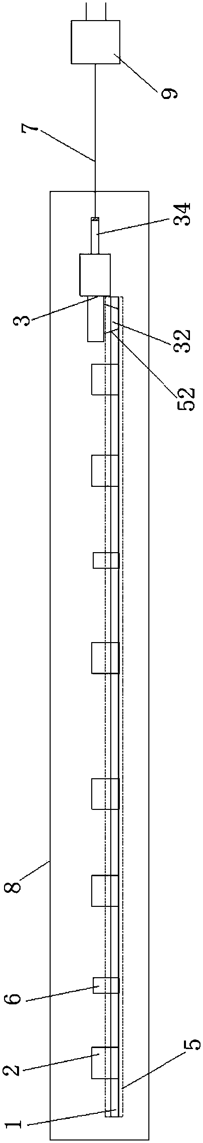
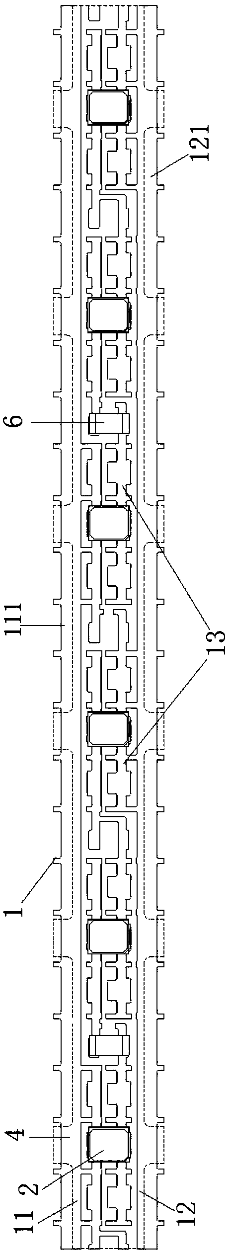
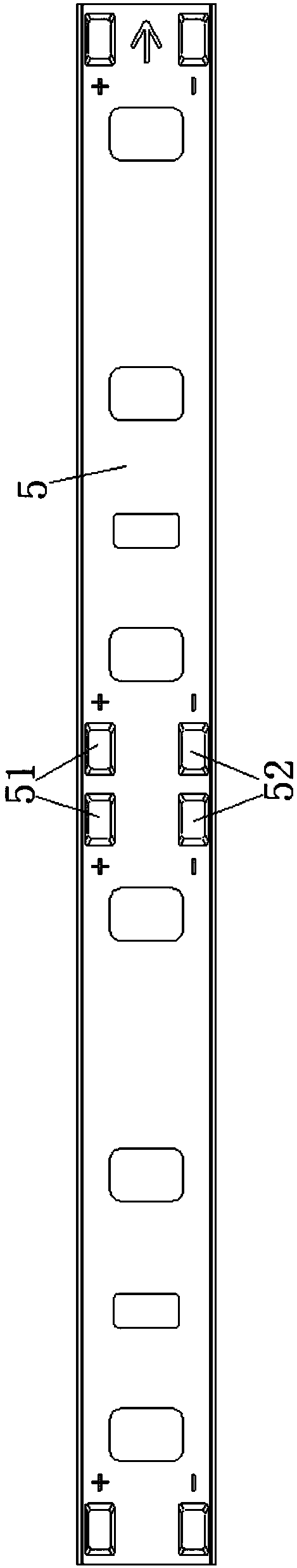
[0031] Such as Figure 1 to Figure 4 As shown, an LED light strip includes a line strip 1, a lamp bead 2, a conversion plug 3, a power cord 7, and a packaging jacket 8. The line strip 1 is integrally stamped and formed by a bendable conductive metal strip. The belt 1 is provided with two first power supply lines 11 and second power supply lines 12 arranged in parallel directions, and a plurality of component lines 13 connected in parallel between the first power supply lines 11 and the second power supply lines 12, Each of the component lines 13 is provided with a plurality of lamp bead installation areas arranged at equal intervals along the longitudinal direction of the line strip 1 and can be connected in series by the lamp beads 2. The lamp beads 2 are mounted on the lamp on the bead mounting area.

[0032] The circuit belt 1 in the present invention is integrally punched and formed by a bendable conductive metal belt. The overall circuit layout is accurate and stable, an...

Embodiment 2

[0042] Compared with Embodiment 1, the main difference is that when the output voltages of the first power supply line 11 and the second power supply line 12 are greater than the sum of the rated voltages of the lamp beads 2 of each element line 13, the The LED light strip further includes a resistance element 6 mounted on the element line 13 and connected in series with the lamp bead 2 of the same element line 13 . By setting the resistance element 6, it can act as a voltage divider to prevent the actual voltage of the lamp bead 2 from being higher than the rated voltage, thereby damaging the lamp bead 2, and avoiding potential safety hazards caused by long-term use.

[0043] The transparent insulating film 4 covers the entire outer surfaces of the element circuit 13 , the lamp bead 2 and the resistance element 6 and part of the outer surfaces of the first power circuit 11 and the second power circuit 12 . Since there are many disconnected or punched areas between the compone...


PUM


Abstract

The invention relates to an LED lamp band comprising a circuit band, lamp beads, a changeover plug, a power wire and an encapsulation sleeve. The circuit band is formed in the manner that overall punching is conducted on a bendable conductive metal band. Element circuits are connected between a first power circuit and a second power circuit of the circuit band. Each element circuit is provided with lamp bead installation areas. The circuit band is covered with a transparent insulated film and a plastic protective layer. The areas, not covered by the transparent insulated film, of the first power circuit and the second power circuit are used as a positive electrode connection area and a negative electrode connection area. Positive terminals and negative terminals are arranged on the plasticprotective layer. A first positive pin and a first negative pin of the changeover plug are welded to the positive terminals and the negative terminals correspondingly. A second positive pin and a second negative pin of the changeover plug are connected with one end of the power wire. The other end of the power wire is provided with a plug used for being connected with the mains supply. The circuit band and the changeover plug are arranged in the transparent encapsulation sleeve. The LED lamp band has the advantages of being free of a printed circuit, less in pollution and low in cost.

Description

technical field [0001] The invention relates to the field of lighting equipment, more specifically, to an LED light strip. Background technique [0002] LED light strips are more and more widely used in the decorative lighting market due to their long service life, energy saving and environmental protection. The current LED flexible light strips are usually composed of lamp beads and flexible printed circuit boards (FPC for short). However, in the production process of flexible circuit boards, various heavy metals and organic wastewater are discharged, the composition is complex, and the treatment is difficult. If the metals in the waste liquid and wastewater are discharged without treatment, it will cause waste. And pollute the environment. And the production of flexible circuit boards (single-sided system) mainly includes cutting, drilling, pasting dry film, alignment, exposure, development, etching, stripping, surface treatment, pasting cover film, pressing, curing, surf...

Claims


Application Information

Patent Timeline
Patent Type & Authority Applications(China)
IPC IPC(8): F21S4/24F21V19/00F21V23/00F21V23/06F21V23/02F21V15/00F21Y103/10F21Y115/10
CPCF21S4/24F21V15/00F21V19/0025F21V23/002F21V23/02F21V23/06F21Y2115/10F21Y2103/10
Inventor 周拥军吴少健
Owner 杭州小太阳农业科技有限公司
Why Eureka
Try Eureka