Simple polishing machine for the production of piano shell parts

A technology for parts and polishing machines, which is applied to surface polishing machine tools, grinding/polishing equipment, metal processing equipment, etc. High work efficiency and good workpiece surface quality

Active Publication Date: 2017-01-04
肇庆市华悦钢琴乐器有限公司
View PDF7 Cites 0 Cited by
  • Summary
  • Abstract
  • Description
  • Claims
  • Application Information

AI Technical Summary

Problems solved by technology

Therefore, for parts with such uneven surfaces or curved surfaces, in the prior art, workers are completely hand-grinding and polishing, and the work efficiency is low, the labor intensity of workers is high, and the surface quality is poor.

Method used


Image

  • Simple polishing machine for the production of piano shell parts
  • Simple polishing machine for the production of piano shell parts
  • Simple polishing machine for the production of piano shell parts

Examples


Embodiment 1

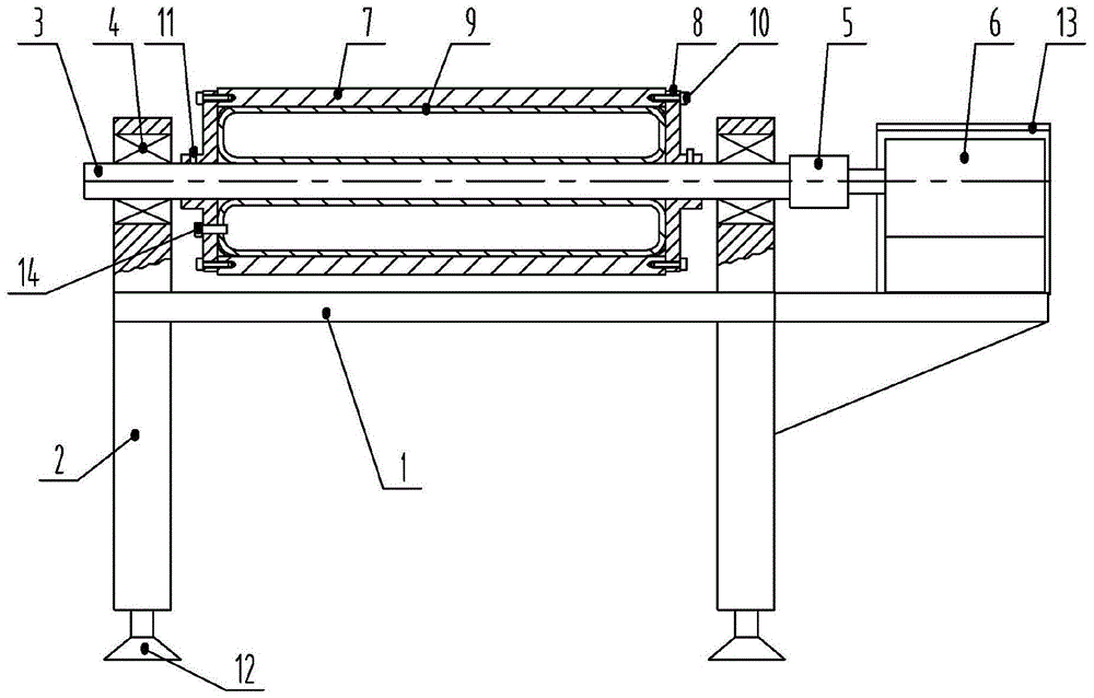
[0031] see figure 1 , in the figure, the present invention is used for the simple polishing machine of piano shell parts production, comprises workbench 1, and four corners of the bottom of workbench are provided with outrigger 2, and polishing roller is installed above the workbench, and the two ends of polishing roller pass bearing and bearing seat 4 Rotate and support on the workbench, and one end of the polishing roller is directly connected with the driving motor 6 through the shaft coupling 5, the polishing roller includes the rotating shaft 3 and the roller body 7, and the two ends of the roller body are fixedly provided with end caps 8. An airtight chamber is formed between the body, both end covers and the rotating shaft, and an annular air bag 9 is arranged in the airtight chamber, and an air nozzle 14 is arranged on the air bag, and the air nozzle protrudes from the end cover, and the air bag completely fills the entire airtight chamber when it is full of air , the ...

Embodiment 2

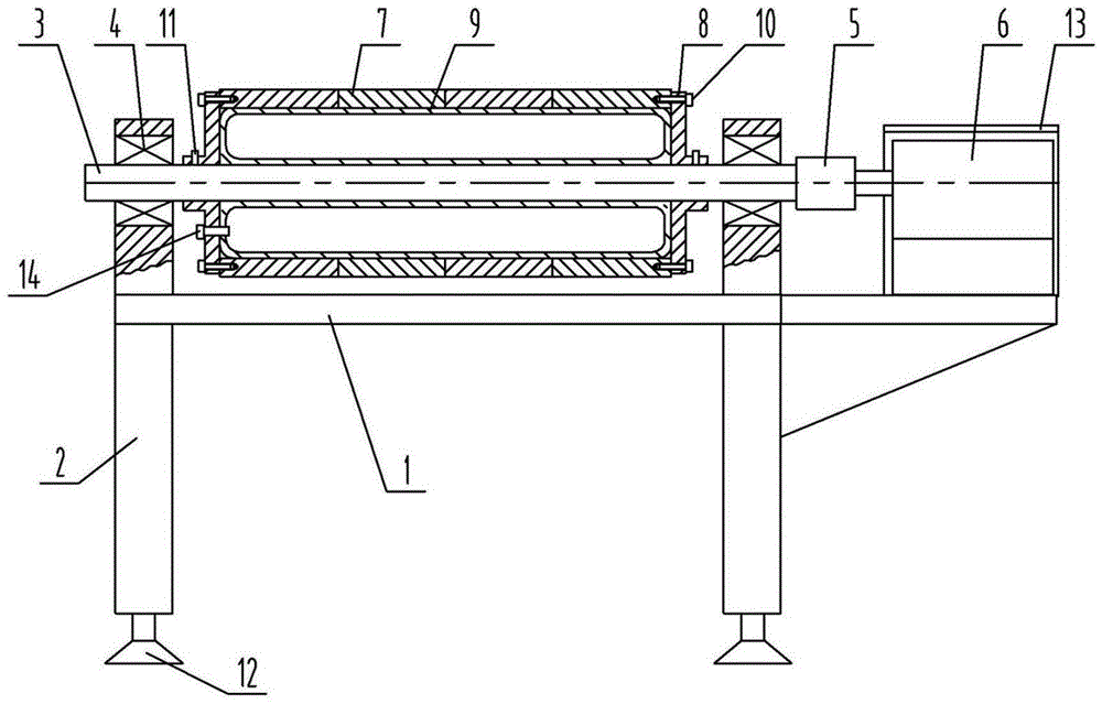
[0035] see figure 2 , Figure 4 , the structure of this embodiment is similar to that of Embodiment 1, and the same numbers in the figure represent the same meaning, which will not be repeated here. The difference is that the roller body described in this embodiment is composed of multiple sections connected in series; Screw connection between.

[0036] Compared with Embodiment 1, the roller body of this embodiment is composed of multiple sections connected in series. According to the width of the workpiece to be processed, the length of the roller body can be adjusted accordingly, so as to prevent the length direction of the surface of the roller body from being too long due to unused places, which will affect the operation of workers. , so it is more convenient to use.

Embodiment 3

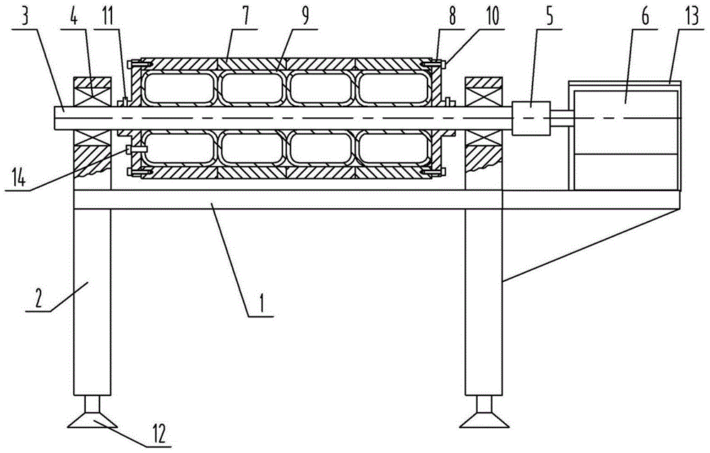
[0038] see figure 2 , Figure 5 , the structure of this embodiment is similar to that of Embodiment 2, and the same numbers in the figure represent the same meaning, which will not be repeated here. Teeth and matching grooves snap together.

[0039] Compared with Embodiment 2, when the segmented roller bodies of this embodiment are connected in series, two adjacent segments are locked together by a plurality of protruding teeth uniformly distributed on the end surfaces and matching grooves. The realized functions are the same, only the specific means of implementation are different.


PUM


Abstract

The invention relates to a simple polishing machine, in particular to a simple polishing machine used for the production of piano shell parts. Including the workbench, the four corners of the bottom of the workbench are provided with outriggers, and the polishing roller is installed above the workbench. motor, the polishing roller includes a rotating shaft and a roller body, the two ends of the roller body are fixedly provided with end covers, and a closed chamber is formed between the roller body, the two end covers and the rotating shaft, and an annular air bag is arranged in the airtight chamber, and an air bag is arranged on the air bag Nozzle, the air nozzle protrudes from the end cover, and the air bag completely fills the entire airtight chamber when it is full of air, and the thickness of the roller body is 3-10mm. The invention is suitable for adjusting and polishing uneven surfaces or curved surfaces, and has good surface quality, high work efficiency, significantly reduced labor intensity of workers, convenient use, safe and reliable performance, and is suitable for popularization and implementation.

Description

technical field [0001] The invention relates to a simple polishing machine, in particular to a simple polishing machine used for the production of piano shell parts. Background technique [0002] The casing of the piano includes a top cover, a keyboard cover, an upper door panel, a lower door panel and side panels. The function of the shell is to stabilize the keyboard mechanism, pedal mechanism and tension string structure, prevent dust from entering, and ensure that internal parts are not damaged. Plus, it boosts volume and makes the tone more pleasing to the ear. Since Steinway successfully used plywood to make piano shells in 1880, this method has been widely used by piano factories all over the world. Today, almost all pianos are made of plywood. [0003] For some small irregular parts in the piano shell, such as the piano feet, the surface is not smooth, or the local surface is curved, and the existing automatic plane polishing machine is not suitable for its polish...

Claims


Application Information

Patent Timeline
Patent Type & Authority Patents(China)
IPC IPC(8): B24B29/02
Inventor 王惠忠
Owner 肇庆市华悦钢琴乐器有限公司
Why Eureka
Try Eureka