
Flexible transmission device for workpiece annealing

A flexible transmission and annealing technology, applied in rolling contact bearings and other directions, can solve the problems of friction between workpiece and positioning tooling, low product processing efficiency, troublesome debugging and adjustment, etc., to achieve smooth rotation, excellent effect, and convenient disassembly and assembly.

Active Publication Date: 2014-12-17
AEROSPACE PRECISION PROD INC LTD
View PDF7 Cites 3 Cited by
  • Summary
  • Abstract
  • Description
  • Claims
  • Application Information

AI Technical Summary

Problems solved by technology

However, in the current annealing device that does not use positioning tooling, the coaxiality of the workpiece, the driving motor spindle, and the heating coil can only reach about 0.25 mm, and the debugging and adjustment in the production process are more troublesome, resulting in product processing efficiency. Low, the pass rate is also low
The annealing device using the positioning tool basically adopts a rigid transmission spindle. During the processing, due to the deviation of the coaxiality, the workpiece will swing in a conical shape, which will cause severe friction between the workpiece and the positioning tool, and a long time Friction can scratch the surface of the product
In the face of the above situation, using the traditional universal coupling flexible transmission scheme can solve the rigidity problem in the middle part, but the end of the transmission shaft is still a rigid bearing, so it still cannot fundamentally solve the friction problem during transmission

Method used


Image

  • Flexible transmission device for workpiece annealing
  • Flexible transmission device for workpiece annealing
  • Flexible transmission device for workpiece annealing

Examples


Embodiment Construction

[0031] Specific embodiments of the present invention will be described in detail below in conjunction with the accompanying drawings.

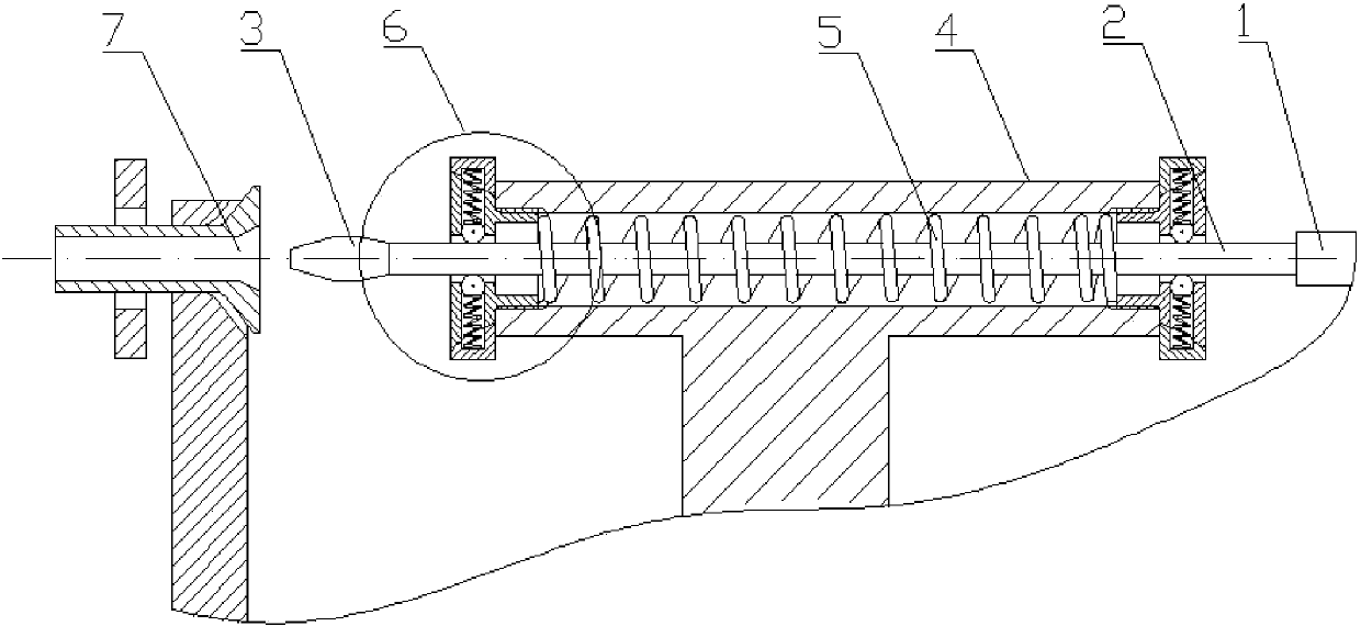
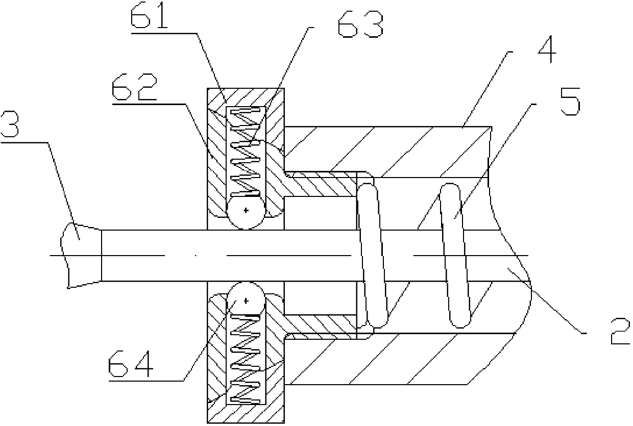
[0032] Such as figure 1 As shown, a flexible transmission device for workpiece annealing includes a flexible shaft 2 , a hollow sleeve 4 and a flexible bearing assembly 6 .

[0033] The flexible shaft 2, which is a hollow shaft made of non-metallic material, is located in the inner cavity of the hollow sleeve 4, and both ends of the hollow sleeve 4 are screwed to the flexible bearing assembly 6, which supports the flexible bearing assembly 6. The flexible shaft 2 is connected to the thimble 3 and the motor output shaft 1 at both ends of the flexible shaft 2 passing through the hollow sleeve 4, and the thimble 3 can be threaded or knurled.

[0034] The non-metallic hollow shaft of the flexible shaft 2 is designed to better ensure its flexibility and form a non-rigid output when the flexible shaft 2 rotates.

[0035] The inner cavity of the ho...


PUM


Abstract

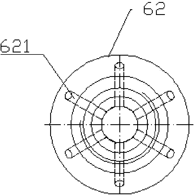
The invention provides a flexible transmission device for workpiece annealing. The flexible transmission device comprises a flexible shaft, a hollow sleeve and a flexible bearing assembly, wherein the flexible shaft is positioned in an inner cavity of the hollow sleeve; the end surface of the hollow sleeve is connected with the flexible bearing assembly; the flexible shaft is supported by the flexible bearing assembly; the flexible bearing assembly comprises an outer retainer ring and an inner bushing in matched connection, and a steel ball; the inner bushing is a hollow cylinder; a mounting hole is formed in the inner wall of the inner bushing; the diameter of the mounting hole communicated with a cavity of the inner bushing is smaller than the diameter of the other part of the mounting hole and the diameter of the steel ball; the outer retainer ring is a hollow cylinder fitting the inner bushing; a mounting groove communicated with the mounting hole of the inner bushing is formed in the inner wall of the outer retainer ring; a flexible compression spring is arranged in the mounting hole and the mounting groove communicated with each other; one end of the flexible compression spring is connected with the steel ball; and the steel ball is positioned in the mounting hole. The flexible transmission device guarantees no damage of workpieces from a fixed part in processing.

Description

technical field [0001] The invention belongs to the field of workpiece annealing, in particular to a flexible transmission device for workpiece annealing. Background technique [0002] At present, the annealing process of the workpiece mainly adopts the method of induction heating, that is, the workpiece is placed in the induction coil to be rotated and heated, but for small-sized workpieces, the coaxiality between the workpiece and the coil is required to be within 0.05mm during annealing. However, in the current annealing device that does not use positioning tooling, the coaxiality of the workpiece, the driving motor spindle, and the heating coil can only reach about 0.25 mm, and the debugging and adjustment in the production process are more troublesome, resulting in product processing efficiency. Low, the pass rate is also low. The annealing device using the positioning tool basically adopts a rigid transmission spindle. During the processing, due to the deviation of th...

Claims


Application Information

Patent Timeline
Patent Type & Authority Applications(China)
IPC IPC(8): F16C23/06
Inventor 桂林景申庆援刘如刚郭双双柳阳阳齐跃
Owner AEROSPACE PRECISION PROD INC LTD
Learn More