An electronically controlled two-way three-state clutch

A clutch and electronic control technology, applied in the field of mechanical transmission, can solve problems such as complex clutch structure

Inactive Publication Date: 2016-12-28
王陈梓
View PDF9 Cites 0 Cited by
  • Summary
  • Abstract
  • Description
  • Claims
  • Application Information

AI Technical Summary

Problems solved by technology

[0002] At present, there are many types of clutches on the market, and most of the clutches involving forward and reverse bidirectional three-state clutches have complex structures. The present invention proposes an electronically controlled bidirectional three-state clutch with a simple structure, which is mainly composed of electronically controlled power input shafts, forward rotation Composition of power output body, shaft sleeve with external thread, reverse power output body and transition body

Method used


Image

  • An electronically controlled two-way three-state clutch

Examples


Embodiment Construction

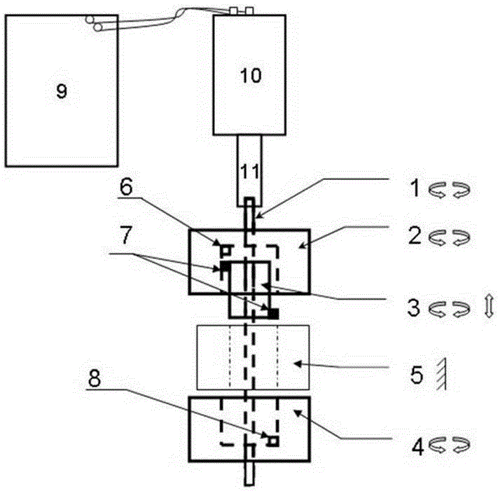
[0012] Combine below figure 1 Further detailed description of the embodiments of the patent of the present invention.

[0013] combine figure 1 , an electronically controlled two-way three-state clutch of the patent of the present invention is mainly composed of an electronically controlled power input shaft [1], a positive rotation power output body [2], a shaft sleeve with external threads [3], and a transition body [5] Composed of the reverse power output body [4], the shaft sleeve [3] with external thread is first set on the electric control power input shaft [1], and then the forward rotation power output body [2], transition body [5] , reverse power output body [4] suits above them successively. Among them, the inner hole of the shaft sleeve [3] with external thread is set as a square hole, which cooperates with the square cylindrical surface of the electric control power input shaft [1], and the two can only slide freely along the rotation axis and cannot rotate relat...


PUM


Abstract

The invention relates to an electronically controlled two-way three-state clutch. When realizing the two-way three-state clutch control of forward and reverse transmission and separation, most of the clutch structures are complicated. It consists of forward rotation power output body, reverse power output body and transition body. Driven by the controllable rotation of the electronically controlled power input shaft, when the shaft sleeve with external thread is screwed into the internal thread of any one of the forward and reverse power output bodies, it passes through the stop surfaces set on both sides. Fit and drive together to realize forward and reverse transmission; when the shaft sleeve with external thread rotates under the accurate position control of the electronically controlled power input shaft and slides axially to the relatively static transition body position in the middle of the forward and reverse power output bodies , the electronic control power input shaft is separated from the forward and reverse power output bodies, so that the two-way three-state clutch of one clutch and two clutches can be realized through the coordinated action of mechanical and electronic control integration.

Description

technical field [0001] The patent of the invention relates to an electronically controlled two-way three-state clutch, which belongs to the technical field of mechanical transmission. Background technique [0002] At present, there are many types of clutches on the market, and most of the clutches involving forward and reverse bidirectional three-state clutches have complex structures. The present invention proposes an electronically controlled bidirectional three-state clutch with a simple structure, which is mainly composed of electronically controlled power input shafts, forward rotation It consists of a power output body, a shaft sleeve with external threads, a reverse power output body and a transition body. The shaft sleeve with external thread is sleeved on the electric control power input shaft, and the contact surface between the two restricts it to slide relative to the axial direction. Driven by the rotation of the electronically controlled power input shaft, whe...

Claims


Application Information

Patent Timeline
Patent Type & Authority Patents(China)
IPC IPC(8): F16D28/00
Inventor 王陈梓
Owner 王陈梓
Why Eureka
Try Eureka