Underpower millimeter-wave ceiling metering method

A millimeter-wave, low-power technology, applied in the field of low-power millimeter-wave cloud measurement, to achieve the effect of large detection effect

Active Publication Date: 2014-12-17
XIAN HUATENG MICROWAVE
View PDF4 Cites 6 Cited by
  • Summary
  • Abstract
  • Description
  • Claims
  • Application Information

AI Technical Summary

Problems solved by technology

[0003] The purpose of the present invention is to provide a low-power millimeter-wave cloud measurement method to solve the cloud measurement effect of traditional high-power millimeter-wave using lower-power millimeter-wave

Method used


Image

  • Underpower millimeter-wave ceiling metering method
  • Underpower millimeter-wave ceiling metering method
  • Underpower millimeter-wave ceiling metering method

Examples


Embodiment Construction

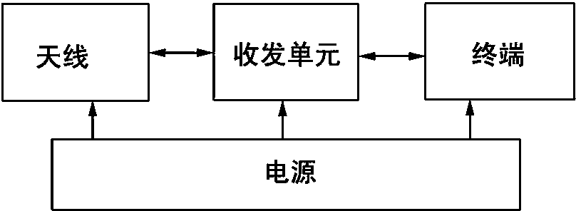
[0011] The low-power millimeter-wave cloud measuring instrument of the present invention is composed of an antenna, a transceiver unit, a power supply and a terminal.

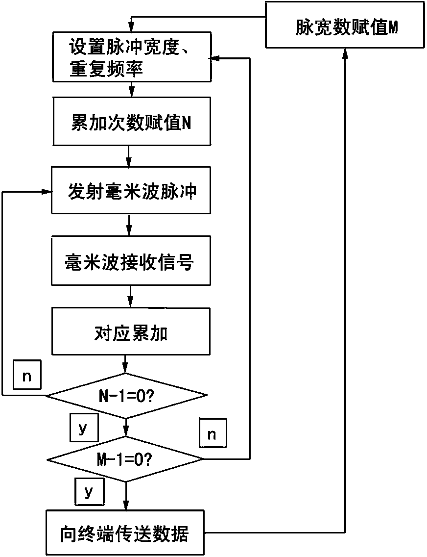
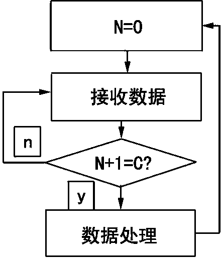
[0012] see figure 1 , the antenna consists of a reflector and a feed source, used to transmit and receive millimeter wave signals, and the antenna is fixed to the sky. The transceiver unit generates a stable modulated millimeter-wave signal, radiates it to the air through the antenna, and then receives the millimeter-wave signal from the antenna and scattered by the cloud, decodes and converts it into a numerical signal, and sends it to the terminal after corresponding accumulation. It is a microcomputer. The terminal completes signal power spectrum analysis, spectrum accumulation, and identification of cloud feature quantities (cloud base height, cloud top height). Displays cloud outlines. The terminal also sets the transceiver unit, and sets the transmit pulse width and pulse repetition frequency of the tr...


PUM


Abstract

The invention discloses an underpower millimeter-wave ceiling metering method. The underpower millimeter-wave ceiling metering method adopts an underpower millimeter-wave ceilometer composed of an antenna, a transceiving unit, a power source and a terminal. The transceiving unit generates stable modulated millimeter wave signals which are radiated to the air through the antenna and received by the antenna, then the millimeter wave signals returned by cloud scattering are decoded and converted into numerical signals, and the numerical signals are correspondingly accumulated to be transmitted to the terminal; the terminal analyzes signal power spectrums, the signal power spectrums are accumulated to identify cloud characteristic quantity; transmission pulse width and pulse repetition rate of the transceiving unit are set by the terminal. By the underpower millimeter-wave ceiling metering method, conventional high-power millimeter-wave ceiling metering effect can be achieved by underpower millimeter waves.

Description

technical field [0001] The invention belongs to a meteorological measuring method. Background technique [0002] Traditional laser nephelographs use visible or near-infrared lasers to detect clouds. The wavelength of the laser is on the order of microns. Since the wavelength is smaller than the diameter of cloud particles, it cannot penetrate clouds in most cases and can only detect cloud bases. Aerosols in the atmosphere can also attenuate the laser, so in hazy weather, the detection ability is seriously reduced, and even clouds cannot be detected. The attenuation of millimeter waves by aerosols can be ignored, and the attenuation of cloud particles is much smaller than that of lasers. It can detect clouds well, and obtain cloud bases and cloud structures. Traditional millimeter wave detection often needs to emit millimeter electromagnetic waves with a peak value of several hundred watts to more than ten kilowatts, or even larger. Contents of the invention [0003] The ...

Claims


Application Information

Patent Timeline
Patent Type & Authority Applications(China)
IPC IPC(8): G01S7/483G01S17/95
CPCG01S7/28G01S13/95Y02A90/10
Inventor 高玉春马舒庆刘丽华陈炎王钢何建新谢承华王文明
Owner XIAN HUATENG MICROWAVE
Why Eureka
Try Eureka