Wiring method and device

A wiring method and wiring technology, applied in special data processing applications, instruments, electrical digital data processing, etc., can solve problems such as prolonging the design cycle, not proposing a solution, and long design cycle

Active Publication Date: 2014-12-17
JEDAT SOFTWARE BEIJING CO LTD
View PDF2 Cites 16 Cited by
  • Summary
  • Abstract
  • Description
  • Claims
  • Application Information

AI Technical Summary

Problems solved by technology

However, in the current liquid crystal panel design process, the wiring process mainly relies on manual or some simple auxiliary tools to complete the drawing of the layout. Due to the extremely high complexity of the wiring task itself, the wiring workload is heavy, error-prone, and the design cycle is long. Once the layout is slightly changed, it basically needs to be redesigned, which puts a lot of pressure on the designers, and also prolongs the design cycle and increases the design cost.
[0004] Since the layout design tools of integrated circuits (IC) are basically used in the current LCD panel design, in the field of integrated circuit design automation, although the automatic router products for ICs are very mature, due to the influence of LCD panel wiring The environment and the specific goals of LCD panel wiring (for example, it is required to support arbitrary angle wiring, wiring adapts to the limitations of the outer contour of the Panel (ie, panel), variable line width, equal resistance connection, etc.), IC wiring tools cannot effectively solve the liquid crystal wiring problem
[0005] Aiming at the problems existing in the wiring method in the related art, no effective solution has been proposed yet

Method used


Image

  • Wiring method and device
  • Wiring method and device
  • Wiring method and device

Examples


Embodiment Construction

[0077] It should be noted that, in the case of no conflict, the embodiments in the present application and the features in the embodiments can be combined with each other. The present application will be described in detail below with reference to the accompanying drawings and embodiments.

[0078] In the following description, unless indicated otherwise, various embodiments of the present application are described with reference to acts and symbolic representations of operations that are performed by one or more computers. Among them, computers include various products such as personal computers, servers, and mobile terminals, and devices using CPUs, single-chip microcomputers, DSPs, and other processing chips can be called computers. It will thus be appreciated that such acts and operations, which are sometimes referred to as computer-implemented, include the manipulation of electrical signals representing data in a structured form by the processing unit of a computer. This...


PUM


Abstract

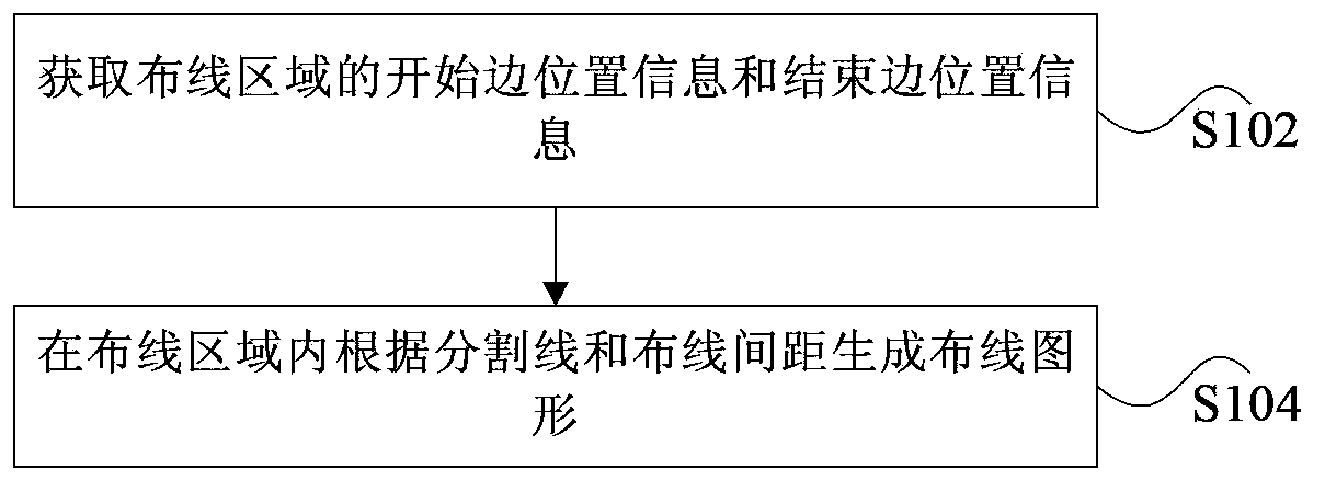
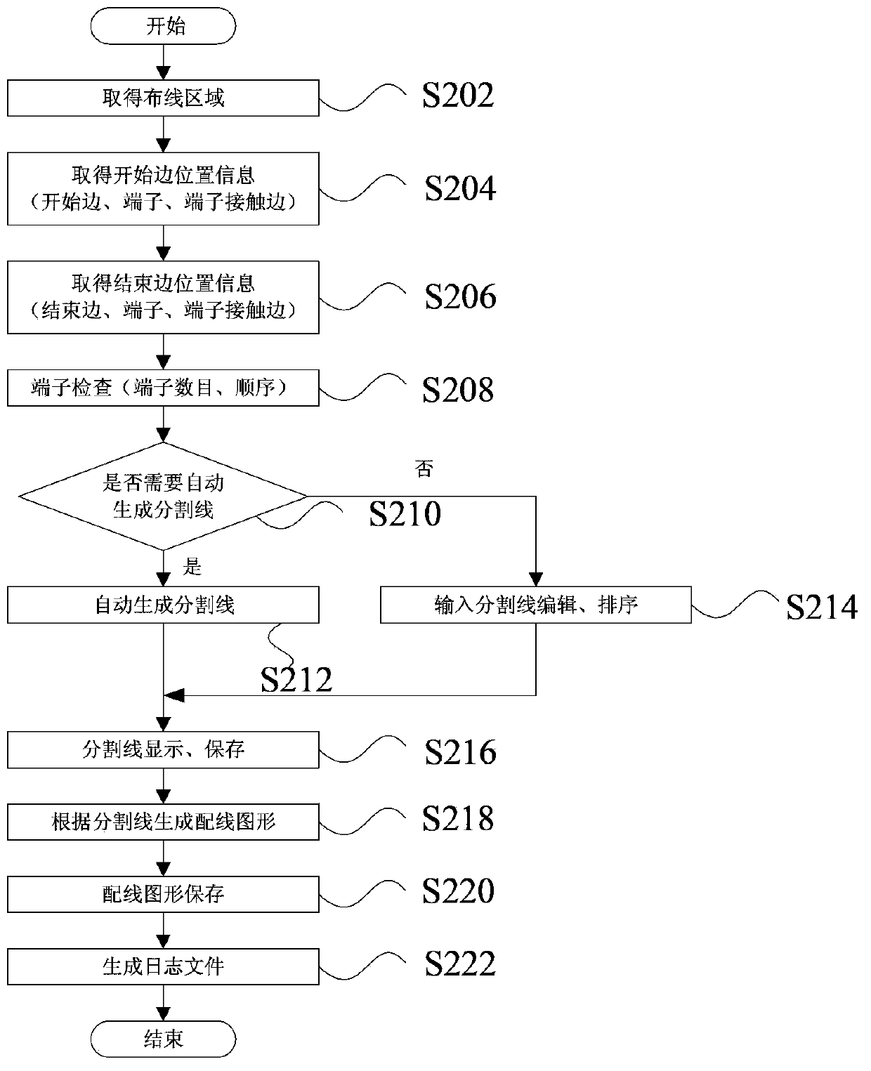
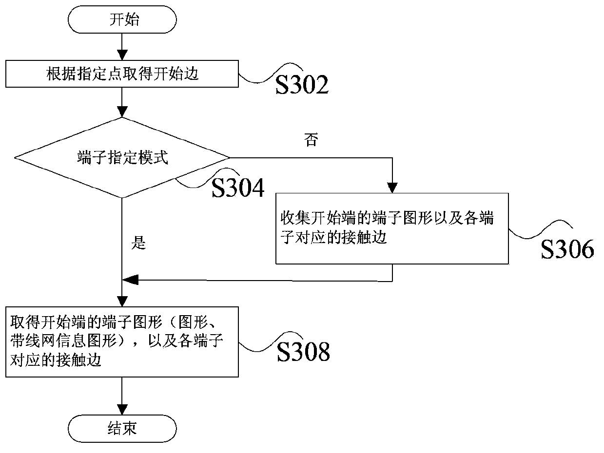
The invention discloses a wiring method and device. The wiring method comprises the steps that start edge position information and end edge position information of a wiring area are acquired, wherein the start edge position information comprises start edge information, start terminal information as well as start terminal and start edge contact information, the end edge position information comprises end edge information, end terminal information as well as end terminal and end edge contact information, and one or more start terminals and end terminals are provided; a wiring graph is generated in the wiring area according to a cutting line and a wiring interval; the wiring graph is used for indicating wiring between the start terminal and the end terminal; the cutting line comprises a start edge and an end edge. According to the wiring method and device, the problem in a wiring method of a correlation technique is solved, and a new wiring method is provided, so that the wiring quality is improved.

Description

technical field [0001] The present application relates to the field of circuit design, in particular, to a wiring method and device. Background technique [0002] With the rapid development of small and medium-sized panels, the output of touch screens and high-resolution omentum screens has increased sharply, and the requirements for wiring density per unit area, wiring resistance, and capacitance have been greatly increased, and line width and line spacing have also become increasingly. Small, in this case, the designer's design pressure is increasing day by day. [0003] Especially in the wiring stage, the liquid crystal circuit wiring needs to support arbitrary angles, variable line widths, and sharp-angle wiring is prohibited. At the same time, it is required that the wiring be as equal resistance as possible or be connected according to the specified resistance value. However, in the current liquid crystal panel design process, the wiring process mainly relies on manua...

Claims


Application Information

Patent Timeline
Patent Type & Authority Applications(China)
IPC IPC(8): G06F17/50
Inventor 黄文辉徐钢颜能
Owner JEDAT SOFTWARE BEIJING CO LTD
Why Eureka
Try Eureka