A kind of nmos line array image sensor

An image sensor and line array image technology, applied in the field of sensors, can solve the problems of complex drive pulse timing, inability to read out multiple times, and low pixel utilization, and achieve flexible implementation methods, low cost, and simple implementation methods Effect

Inactive Publication Date: 2018-09-14
CHANGCHUN INST OF OPTICS FINE MECHANICS & PHYSICS CHINESE ACAD OF SCI
View PDF5 Cites 0 Cited by
  • Summary
  • Abstract
  • Description
  • Claims
  • Application Information

AI Technical Summary

Problems solved by technology

The segmented integration function is realized by changing the driving timing, and the realization of the driving pulse timing is more complicated; moreover, in a frame of image data, the integration time of different pixels can only increase or decrease monotonously; after valid data is read out, a separate Reset driving pulse sequence; the readout frequency of image data of all pixels depends on the maximum integration time of all pixels, and the image data of pixels with short integration time cannot be read out multiple times within one integration cycle of pixels with long integration time. Low time pixel utilization

Method used


Image

  • A kind of nmos line array image sensor
  • A kind of nmos line array image sensor
  • A kind of nmos line array image sensor

Examples


Embodiment Construction

[0048] The inventive idea of ​​the present invention is:

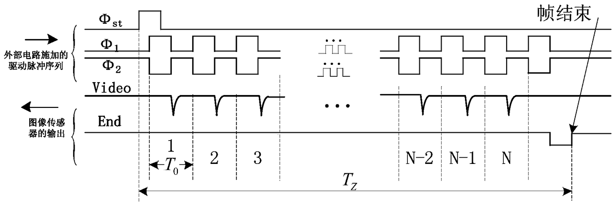
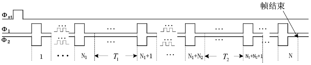
[0049] The reading process of the NMOS linear image sensor is also the process of resetting the pixels. In order to realize the segmented integration function of the sensor, the present invention proposes two pulse sequences (drive pulse sequence 1, drive pulse sequence 2), which are used as Reset pulse sequence and data read pulse sequence.

[0050] The present invention will be described in detail below in conjunction with the drawings.

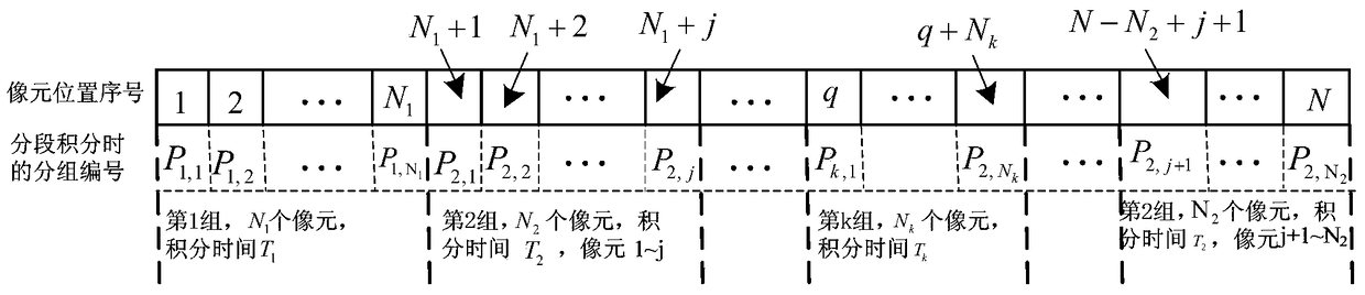
[0051] In order to realize the segmented integration function of the NMOS linear image sensor of the present invention, when designing the driving pulse sequence, it is necessary to first group the pixels of the sensor according to the difference of integration time:

[0052] Such as image 3 As shown, suppose the number of sensor pixels is N, and the position numbers of the pixels on the image sensor are marked as 1, 2,...,N. According to the difference of integration time, all pixels of ...


PUM


Abstract

The present invention relates to an NMOS line array image sensor, comprising: sensor pixels grouped according to integration time; a driving pulse sequence 1 used for initial reset of the image sensor and for normal data readout of the image sensor; Driving pulse sequence 2 of readout pulses for a group of pixel data with the same integration time. The NMOS line array image sensor of the invention has good performance and can improve the signal-to-noise ratio of the output signal of the image sensor.

Description

Technical field [0001] The invention relates to a sensor for measuring the energy of light signals, in particular to an NMOS linear array image sensor. Background technique [0002] The driving pulse sequence of commonly used NMOS linear image sensor is as figure 1 Shown. When the sensor is in use, it needs to provide three-way drive pulse sequence to the sensor, and the corresponding pin is Φ st , Φ 1 , Φ 2 . Among them, Φ 1 , Φ 2 The two signals are completely synchronized, but the phases are exactly opposite. Φ st Start pulse read out for sensor pixel signal, namely Φ st After giving a positive pulse, the video signal Video will be compared with Φ 1 , Φ 2 Synchronous output. After the signals of all pixels are read out, the End of Scan pin and Φ 2 Synchronously output a negative pulse ( image 3 In, End signal). When the video signal of the first pixel appears, Φ 1 , Φ 2 The corresponding pulse period is defined as the pixel readout period 1, and the pixel readout period...

Claims


Application Information

Patent Timeline
Patent Type & Authority Patents(China)
IPC IPC(8): H04N5/374H04N5/378H04N5/353
Inventor 张佩杰宋克非
Owner CHANGCHUN INST OF OPTICS FINE MECHANICS & PHYSICS CHINESE ACAD OF SCI
Why Eureka
Try Eureka