Large flow assembled grinding device for nano sand mill

A grinding device and a sand mill technology, which are used in the field of mixing and dispersing solid powder and liquid, homogenizing, large-flow assembled grinding rotor device, and emulsification, which can solve the problem of high replacement and maintenance costs, and the inability to manufacture large Diameter and large structure size, small grinding energy and other problems, to achieve the effect of improving production efficiency and production quality, stable and efficient grinding process, and good grinding effect

Active Publication Date: 2017-03-29
PUHLER GUANGDONG SMART NANO TECH CO LTD
View PDF9 Cites 0 Cited by
  • Summary
  • Abstract
  • Description
  • Claims
  • Application Information

AI Technical Summary

Problems solved by technology

A traditional grinding machine generally includes a grinding cylinder with a grinding cavity formed inside and a feeding cavity connected to the grinding cavity. There is a grinding rotor driven by the main shaft in the cavity; however, some of the existing grinding rotors directly install grinding blocks on the rotor body, which is not convenient for installation on the one hand, and the grinding effect is not good on the other hand; The rotor adopts an integral ring structure. The biggest defect of this method is that when a certain grinding block needs to be replaced after wear and tear, the entire ring must be replaced, and the cost of replacement and maintenance is high. Among them, the grinding rotor on the stirring shaft is a conventional sand mill. The main core device of the machine is used for grinding, but the existing grinding rotors generally cannot discharge materials smoothly to the outside of the sand mill cavity, the grinding energy is small, the cylinder volume is small, the diameter of the grinding rotor is small, the continuous working time is short, and the material cannot be avoided. Shortcomings such as rapid temperature rise have adverse effects on production
At the same time, for large-scale industrial production, the grinding rotors of structural parts of many special materials cannot be manufactured into large diameters and large structural sizes, resulting in many times nano-grinding can only stay in the laboratory or pilot test stage, losing the meaning of industrial scale production

Method used


Image

  • Large flow assembled grinding device for nano sand mill
  • Large flow assembled grinding device for nano sand mill
  • Large flow assembled grinding device for nano sand mill

Examples


Embodiment Construction

[0021] Below in conjunction with accompanying drawing, the present invention is described in further detail:

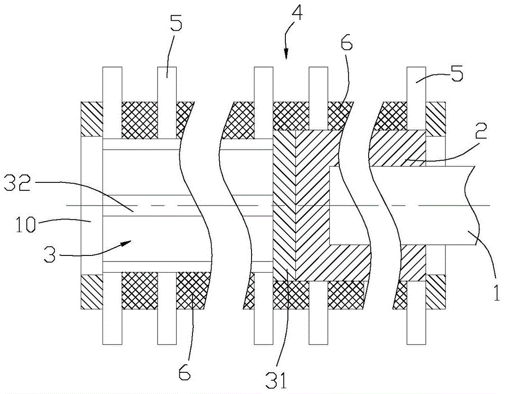
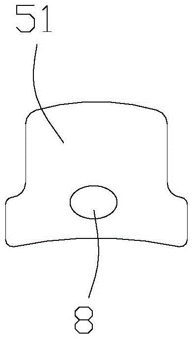
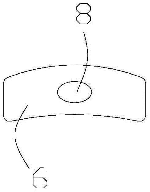
[0022] Such as figure 1 , the grinding rotor of the present invention includes a rotating core 2 that is connected to the main shaft 1 at one end and driven to rotate by the main shaft. The other end of the rotating core is fixed with a hollow grinding frame 3, and a separator is arranged in the grinding frame. The rotating core and the grinding frame form a concentric The rotating body 4 with the same diameter, the rotating core drives the grinding frame to rotate, and several rows of detachable grinding blocks 5 are installed on the peripheral wall of the rotating body along the circumferential direction, and detachable grinding blocks 5 are installed between two adjacent grinding blocks in each row. Isolation block 6; a feed opening is formed between every adjacent two rows of grinding blocks on the grinding rack, and the feeding opening communicates with the inner...


PUM


Abstract

The invention relates to a large-flow split type grinding rotor device. The large-flow split type grinding rotor device comprises a rotating core, wherein one end of the rotating core is connected with a main shaft, the rotating core is driven to rotate by the main shaft, a hollow grinding rack is fixedly arranged on the other end of the rotating core, the rotating core and the grinding rack form a concentric rotating body with the same diameter, a plurality of rows of detachable grinding blocks are circumferentially installed along the circumferential wall of the rotating body, detachable spacing blocks are installed between two adjacent grinding blocks in each row, and material passing openings are formed between every two adjacent rows of grinding blocks and communicated with an inner cavity of the grinding rack. According to a grinding rotor, all of the grinding blocks and the spacing blocks are connected to the rotating body in a sleeved mode, when one grinding block is worn, only the rotor is disassembled, so as to replace the worn grinding block, so that the replacement cost is low. According to the large-flow split type grinding rotor device, the grinding blocks are completely distributed in the whole axial direction of the rotating body, and the grinding blocks are tightly pressed by pressing covers, so that the structure is firm, and the grinding effect is good.

Description

technical field [0001] The present invention relates to the field of ultrafine powder slurry grinding and nano sand mill industrial design, especially to a device for mixing, emulsifying, homogenizing and dispersing solid powder and liquid, and in particular to an innovative wet The large-flow assembled grinding rotor device of the nano-sand mill of the traditional grinding technology. Background technique [0002] With the upgrading of chemical products, the requirements for the production equipment of chemical products are getting higher and higher. After more and more chemical products require nano-quality, more nano-sand mill technology and industrial design issues are placed on the chemical industry. In front of the equipment manufacturer. [0003] In recent years, with the rapid development of the domestic economy and the continuous improvement of people's living standards, in the field of ultra-fine nano-powder production, the quality requirements for the powder itse...

Claims


Application Information

Patent Timeline
Patent Type & Authority Patents(China)
IPC IPC(8): B02C17/16B02C17/18
Inventor 雷立猛
Owner PUHLER GUANGDONG SMART NANO TECH CO LTD
Why Eureka
Try Eureka