Production method for prepreg, and production method for fiber-reinforced composite material

Active Publication Date: 2020-09-03
TORAY IND INC
View PDF0 Cites 1 Cited by
  • Summary
  • Abstract
  • Description
  • Claims
  • Application Information

AI Technical Summary

Benefits of technology

The patent aims to improve the quality and efficiency of producing fiber-reinforced plastic (FRP) by addressing issues such as fuzzing and cleavage caused by abrasion. The invention emphasizes the importance of maintaining the arrangement and rectilinearity of reinforcing fibers, ensuring good resin uniformity, and achieving high production speeds and suppression of contamination. Overall, the invention aims to enhance the production efficiency of prepreg, which is a crucial raw material for FRP production.

Problems solved by technology

Patent Literature 1 discloses a method in which a thermoplastic resin is discharged from a T-die and pressed against a reinforcing fiber sheet, but the method poses a problem in that the reinforcing fibers are more likely to cause cleavage and fuzzing and disturb the arrangement property and rectilinearity.
In addition, the method causes a pool of the discharged resin to be formed on the reinforcing fiber sheet, as described in FIG. 3 in Patent Literature 1, and accordingly, poses a problem in that the basis weight uniformity is more likely to be worsened.
Patent Literature 2 discloses a method in which resin coating by meltblowing and opening of a carbon fiber bundle by airblowing are carried out simultaneously, and accordingly, the method causes the carbon fiber sheet to be curved downward in a resin coating section, as described in FIG. 4 in Patent Literature 2, and thus causes a problem in that the arrangement property and rectilinearity of the carbon fibers are more likely to decrease.
In addition, excessively large airblowing is carried out at the resin coating section, causing the resin to be scattered and thus making it more likely that the device becomes contaminated, and in the fields of industrial production, the number of times of equipment shutdown for cleaning is large, rather causing a problem in that the efficiency and the product quality stability are more likely to decrease.
In addition, together with the problems in that the carbon fiber bundle in the resin coating section becomes curved, thus making the distance between carbon fibers ununiform, and in that airblowing is excessively large, the resin coating is more likely to be ununiform, causing a problem in that the basis weight unevenness of the resin is more likely to be large.

Method used


Image

  • Production method for prepreg, and production method for fiber-reinforced composite material
  • Production method for prepreg, and production method for fiber-reinforced composite material
  • Production method for prepreg, and production method for fiber-reinforced composite material

Examples


example 1

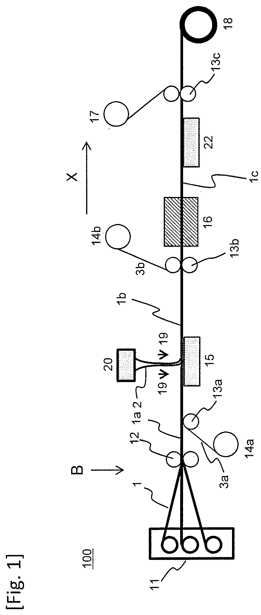
[0077]The process in the present Example is shown in FIG. 1 (however, the impregnation device 16 was not used). Sixty yarns of carbon fiber (T800S-24K, manufactured by Toray Industries, Inc.) were arranged unidirectionally to form a carbon fiber sheet. The carbon fiber sheet had a width of 300 mm. Then, a release paper sheet was inserted onto the lower face of the carbon fiber sheet, the resulting sheet was introduced on a table, and the sheet was conveyed at a speed of 20 m / minute linearly in the coating step viewed straight from the side. Then, using the coating head 20 described in FIG. 1, the carbon fiber sheet was coated with a matrix resin on the table. During this, the coating conditions were as follows. The temperature of the coating head was 85° C., the area per a hole of the nozzle was 0.16 mm2, the through-put-rate per a hole was 1.0 g / minute, and the number of nozzle holes in the width direction was 220. In addition, air was supplied at 0.15 MPa as an air flow, and the c...

example 2

[Example 2] and [Example 3]

[0081]Coating with a matrix resin was carried out in the same manner as in Example 1, and the results were evaluated in the same manner as in Example 1, except that the coating head height was changed as in Table 1 and that the coating height H was changed to 70 mm (Example 2) and 100 mm (Example 3).

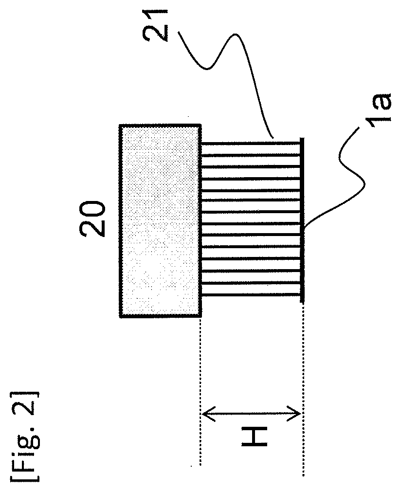
[0082]When the coating was carried out continuously for 10 minutes, the carbon fiber sheet was observed straight from the side, found to have neither laxation nor looseness, and recognized as being linearly conveyed. Next, the coating state was checked by visual observation, and the spinning state was found to be stable. Furthermore, the coating state was observed using a high speed video camera, and in Example 2, the resin fiber was found to have been formed into continuous fibers as in FIG. 2. Furthermore, the fibrous resins were hardly flowing in the horizontal direction, the resin reached linearly from the nozzle to the carbon fiber sheet, and the interval ...

example 4

[0084]Coating with a matrix resin was carried out in the same manner as in Example 1, and the results were evaluated in the same manner as in Example 1, except that the coating head height was changed to 140 mm.

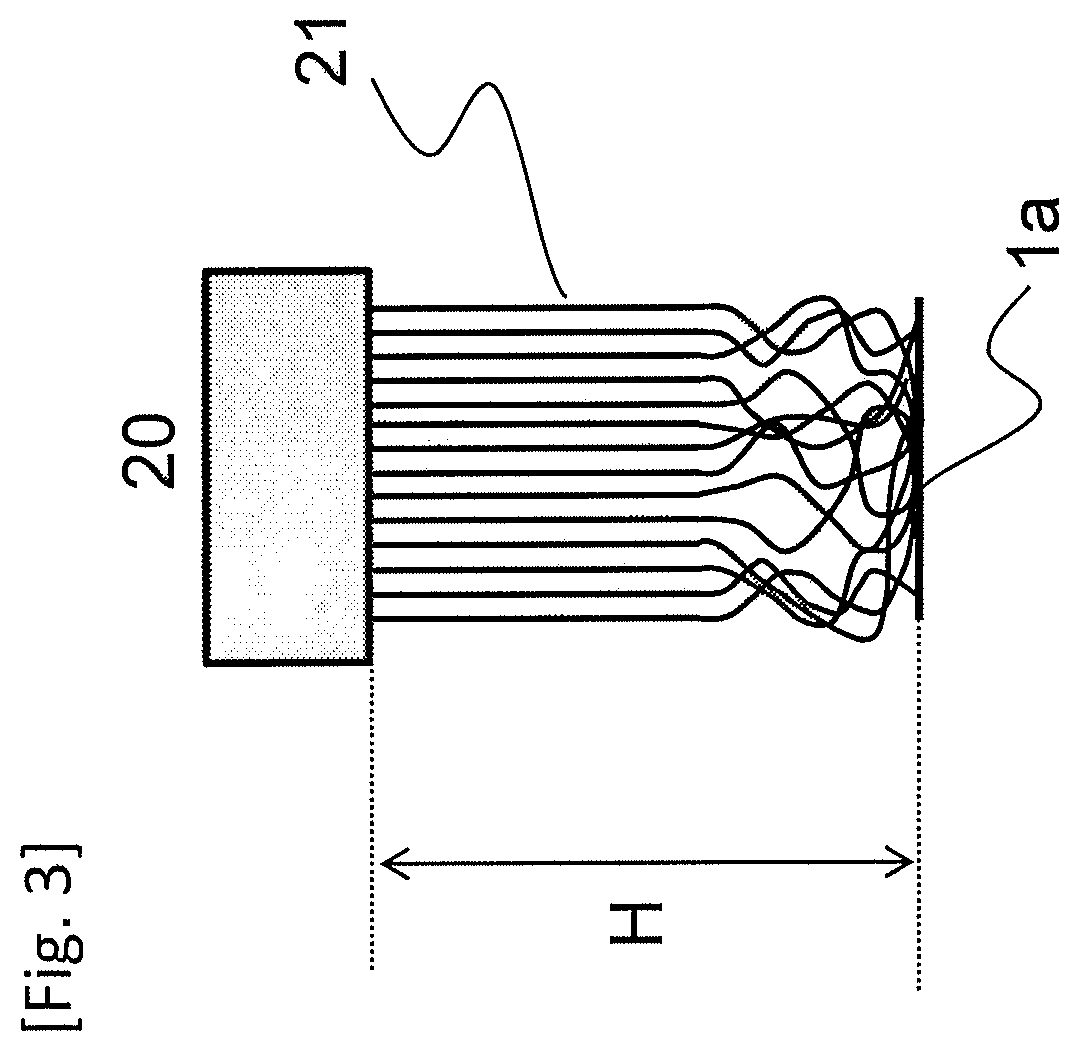
[0085]When the coating was carried out continuously for 10 minutes, the carbon fiber sheet was observed straight from the side, found to have neither laxation nor looseness, and recognized as being linearly conveyed. Next, the coating state was checked by visual observation, and the spinning state was found to be stable. Furthermore, the coating state was observed using a high speed video camera, and the observed state showed that the continuous fibers in the latter half of the spin-line were snaking, and that the fibrous resins were blown by an air flow above the carbon fiber sheet. After the coating, the prepreg conveyance system in the vicinity of the coating device was checked for contamination by visual observation, and almost no contamination was found.

[0086]In addition...


PUM

PropertyMeasurementUnit
Heightaaaaaaaaaa

Abstract

The invention enhances the production efficiency in the production of prepreg by allowing the arrangement property and rectilinearity of reinforcing fibers to be well maintained, allowing the basis weight uniformity of an applied resin to be good, and further allowing a high line speed and suppression of contamination in the process to be achieved. The invention provides a method of producing a prepreg, which includes: discharging a molten resin from a discharge portion; introducing the discharged resin by an air flow; and capturing the discharged resin on a reinforcing fiber sheet conveyed continuously, wherein a key point is that the discharged resin is captured in a region in which the reinforcing fiber sheet is conveyed substantially in planar form.

Description

CROSS REFERENCE TO RELATED APPLICATIONS[0001]This is the U.S. National Phase application of PCT / JP2018 / 006487, filed Feb. 22, 2018, which claims priority to Japanese Patent Application No. 2017-055614, filed Mar. 22, 2017, the disclosures of each of these applications being incorporated herein by reference in their entirety for all purposes.FIELD OF THE INVENTION[0002]The present invention relates to an efficient method of producing a prepreg which is a precursor of a fiber reinforced composite material.BACKGROUND OF THE INVENTION[0003]Fiber reinforced composite materials (FRP) in which a matrix resin containing a thermoplastic resin or a thermosetting resin is reinforced with a reinforcing fiber are used in various fields such as aerospace materials, automobile materials, industrial materials, pressure vessels, construction materials, housings, medical applications, and sports applications. Carbon fiber reinforced materials (CFRP) are widely and suitably used particularly in cases ...

Claims


Application Information

Patent Timeline
IPC IPC(8): C08J5/24B29C70/06B29B15/10
CPCB29C70/06C08J2300/00C08J5/24B29B15/105B29B15/122C08J2363/00C08J2363/02C08J2381/06C08J5/243B29B11/16C08J5/04
Inventor OCHI, TAKASHIAOKI, JUNICHIYAMASHITA, TAKAAKI
Owner TORAY IND INC
Why Eureka
Try Eureka