Connecting rod punch press

A technology of connecting rods and punching machines, which is applied in the direction of punching machines, presses, manufacturing tools, etc., and can solve the problems of unstable repeat positioning accuracy of sliders for mold height adjustment accuracy, inability to ensure the accuracy of stamping and forming products, and unsuitable crank punching machines, etc. To achieve the effect of simplifying structure, ensuring stability and reducing internal structure

Active Publication Date: 2014-12-24
NINGBO CITY COSTON PRECISION MACHINERY
View PDF6 Cites 22 Cited by
  • Summary
  • Abstract
  • Description
  • Claims
  • Application Information

AI Technical Summary

Problems solved by technology

[0002] Punch presses are commonly used equipment in the field of mechanical processing for stamping and forming parts. At present, the general press industry uses crank or eccentric shaft punch presses. The guide guide is connected, and the entire die height adjustment mechanism of the crank punch press is installed inside the slider, and the slider is directly connected with the upper die. When high-temperature stamping products are required, the entire slider mechanism will heat up and contract, and the slider will produce Deformation, resulting in unstable mold height adjustment accuracy and slider repeat positioning accuracy, so that the accuracy of stamped products cannot be guaranteed, so the current crank punch is not suitable for high temperature stamping

Method used


Image

  • Connecting rod punch press
  • Connecting rod punch press
  • Connecting rod punch press

Examples


Embodiment Construction

[0024]The present invention will be further described in detail below in conjunction with the accompanying drawings and embodiments.

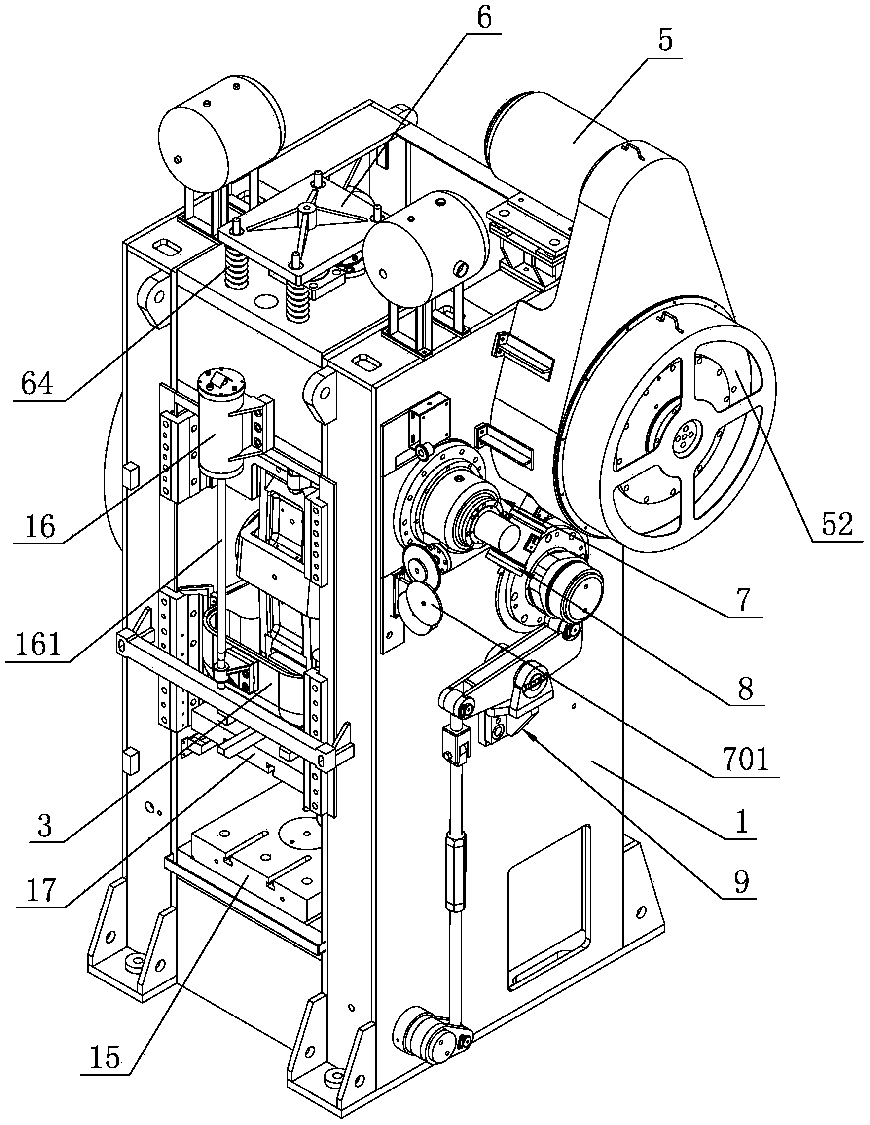
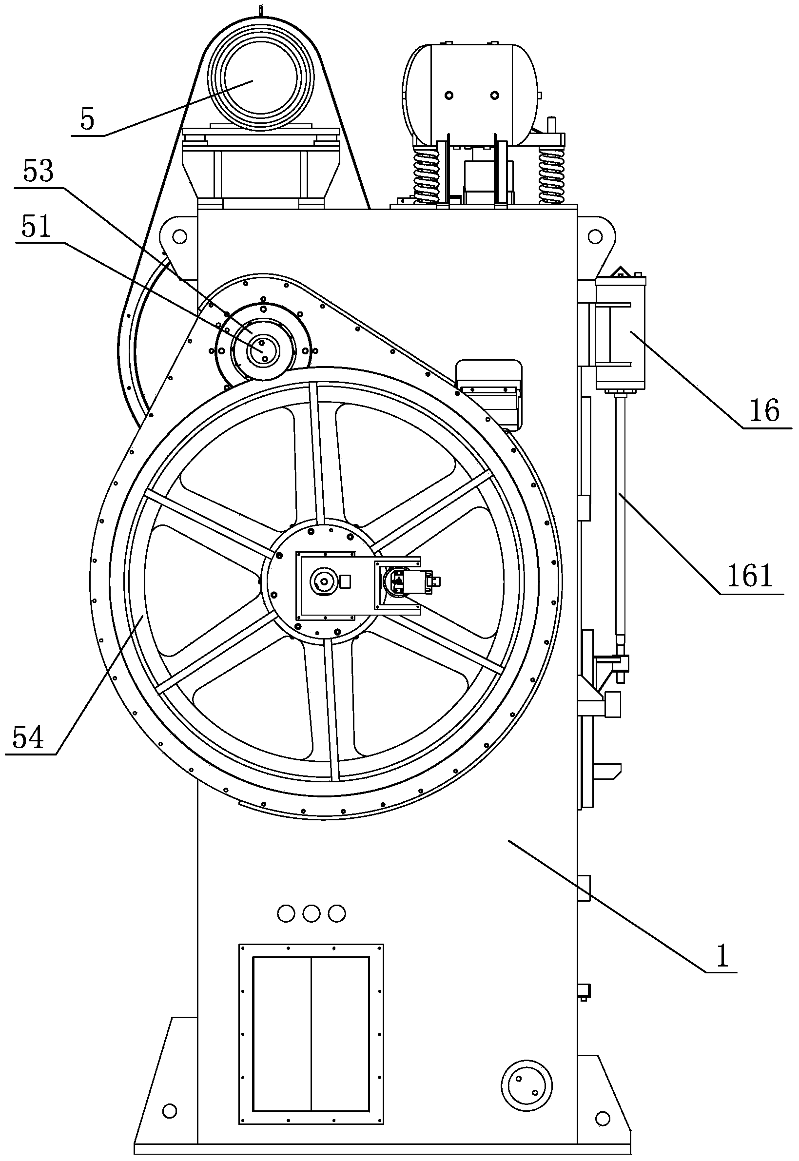
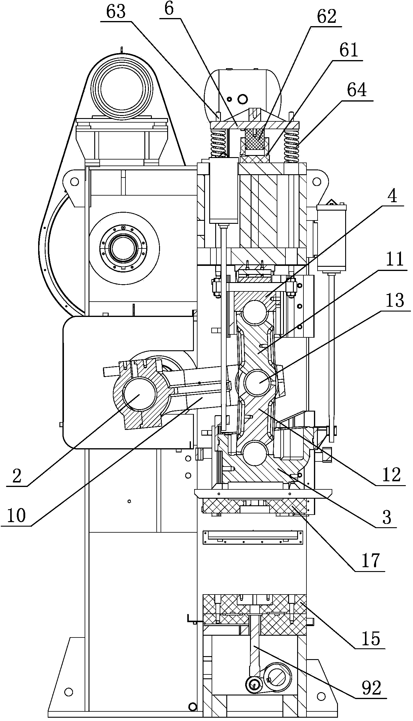
[0025] As shown in the figure, a connecting rod punching machine includes a frame 1, a crankshaft 2, a lower slider 3, an upper slider 4 and a crankshaft rotation driving device, the lower slider 3 is slidably matched with the frame 1, and the crankshaft rotation driving device includes The second motor 5, the first transmission shaft 51, the flywheel clutch 52, the pinion 53 and the bull gear 54, the first transmission shaft 51 is axially connected in the frame 1, the second motor 5 is fixedly installed on the frame 1, and the flywheel clutch 52 and the pinion 53 are coaxially fixedly connected to the first transmission shaft 51 respectively, the second motor 5 and the flywheel clutch 52 are connected through a belt drive assembly (not shown in the figure), the large gear 54 is fixedly connected to the crankshaft 2, and the pinion 53 meshes wi...


PUM


Abstract

The invention discloses a connecting rod punch press, comprising a rack, a crankshaft, a lower slide block, and a crankshaft rotation drive device, wherein the lower slide block is in sliding fit with the rack. The connecting rod punch press is characterized in that an upper slide block is arranged inside the rack; the upper end of the rack is provided with a dynamic balance connecting mechanism of the upper slide block; a first link transmission mechanism is arranged among the crankshaft, the lower slide block and the upper slide block; the rack is provided with an upper slide block adjusting mechanism which is used for adjusting the height of the mold. The connecting rod punch press has the advantages that the upper slide block is arranged inside the rack, the rack is provided with the upper slide block adjusting mechanism which is used for adjusting the height of the mold, and the upper and lower positions of the upper slide block can be adjusted through the adjusting mechanism, thus the height of the mold of the connecting rod punch press is adjusted, meanwhile, the internal structure of the lower slide block is also reduced, the structure of the lower slide block is simplified, the condition that the lower slide block can bear good punching, and does not deform when the connecting rod punch press is used for punching at high temperature is ensured, the punching stability of the punch press and the accuracy of a punched product are ensured, and the connecting rod punch press can be applicable to high-temperature punching.

Description

technical field [0001] The invention relates to a punching machine, in particular to a connecting rod punching machine. Background technique [0002] Punch presses are commonly used equipment in the field of mechanical processing for stamping and forming parts. At present, the general press industry uses crank or eccentric shaft punch presses. The guide guide is connected, and the entire die height adjustment mechanism of the crank punch press is installed inside the slider, and the slider is directly connected with the upper die. When high-temperature stamping products are required, the entire slider mechanism will heat up and contract, and the slider will produce Deformation, resulting in unstable mold height adjustment accuracy and slider repeat positioning accuracy, so that the accuracy of stamped products cannot be guaranteed, so the current crank punch is not suitable for high temperature stamping. Contents of the invention [0003] The technical problem to be solv...

Claims


Application Information

Patent Timeline
Patent Type & Authority Applications(China)
IPC IPC(8): B21D22/02B21D45/02B30B1/26B30B15/00B30B15/02
CPCB30B15/0064
Inventor 严海民李晓华
Owner NINGBO CITY COSTON PRECISION MACHINERY
Why Eureka
Try Eureka