Semiautomatic steel bar bender
A steel bar bending, semi-automatic technology, applied in the field of steel bar bending machine, can solve the problems of not being able to control the bending angle of steel bar well, narrow application range, etc., achieve the effect of low noise, reasonable size and position design, and ensure the forming accuracy
- Summary
- Abstract
- Description
- Claims
- Application Information
AI Technical Summary
Problems solved by technology
Method used
Image
Examples
Embodiment 1
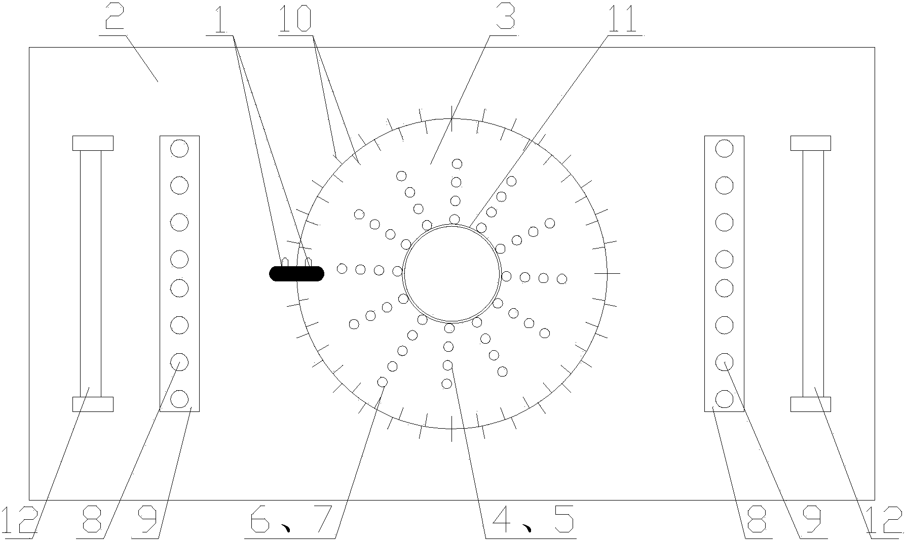
[0023] A semi-automatic steel bar bending machine, such as figure 1 As shown, a machine tool is included, and the upper part of the machine tool is provided with a working plate 2 which is connected to the machine tool. A rotating disk 3 is provided at the center of the working disk 2. The rotating disk 3 is connected to a power mechanism inside the machine tool, and the power mechanism can drive the rotating disk 3 to rotate around its own axis. A number of positioning shaft holes 5 and clamping shaft holes 7 are uniformly distributed on the rotating disk 3 along the circumferential direction of the rotating disk 3, and the distance between the positioning shaft holes 5 and the clamping shaft holes 7 is adapted to the diameter of the steel bar to be bent , A number of positioning shaft holes 5 are distributed in a circle on the rotating disk 3, and the center of the circular positioning shaft holes 5 coincides with the center of the rotating disk 3; the clamping shaft hole 7 ca...
Embodiment 2
[0026] On the basis of the first embodiment, the working disk 2 and the rotating disk 3 are also provided with scale lines 10, and the number of scale lines 10 on the rotating disk is more than the number of scale lines 10 on the working disk 2, and the working disk 2 And the rotating disk 3 are marked with "0" scale line 1.
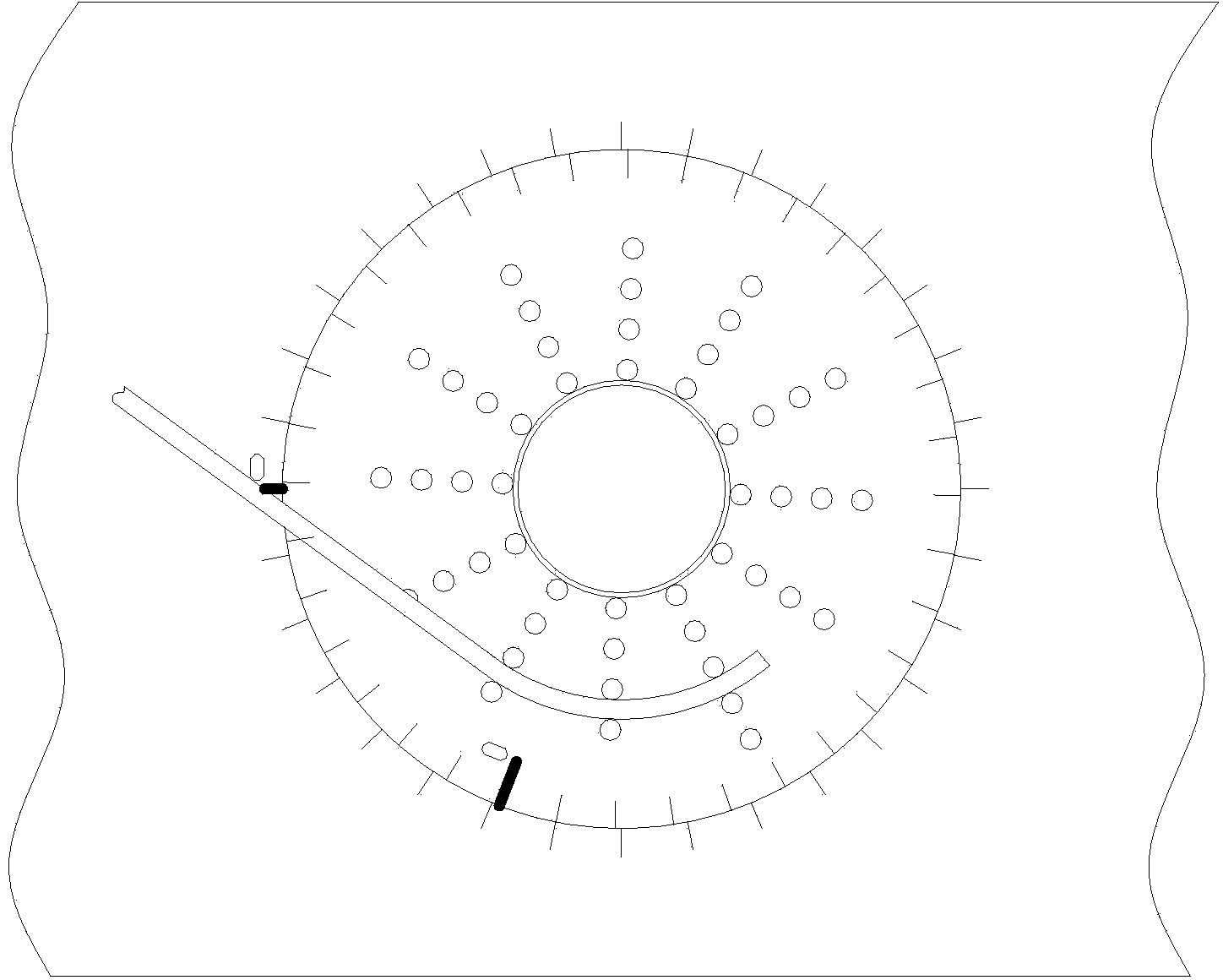
[0027] In this embodiment, the number of scale lines 10 on the working disk 2 is 32, the angle between two adjacent scale lines 10 on the working disk 2 is 11.25°; the number of lines 10 on the rotating disk is 36, The angle between two adjacent graduation lines 10 on the rotating disk is 10°. When the "0" scale line 1 of the working disc 2 and the rotating disc 3 coincide, the angle between the first scale line 10 is 1.25°. Such as figure 1 As shown, at this time, the “0” scale line 1 of the working plate 2 and the rotating plate 3 overlaps, and the steel bar is not bent; but as figure 2 As shown, at this time, the "0" scale line 1 of the working disk 2 ...
Embodiment 3
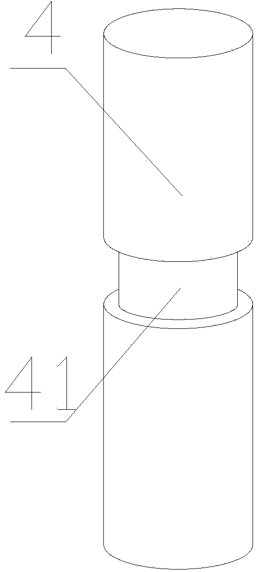
[0029] On the basis of the first or second embodiment, the positioning shaft 4 is provided with a positioning collar 41; the clamping shaft 6 is provided with a clamping collar 61. The positioning clamp ring 41 is set on the positioning shaft 4, which can effectively prevent the steel bar from sliding during the bending process, and ensure the bending accuracy and bending quality of the semi-automatic steel bending machine; the clamp shaft 6 is provided with a clamp clamp ring 61, which can To further prevent the steel bar from sliding during the bending process.
PUM
 Abstract
Description
Claims
Application Information
 - R&D
- Intellectual Property
- Life Sciences
- Materials
- Tech Scout
- Unparalleled Data Quality
- Higher Quality Content
- 60% Fewer Hallucinations
Browse by: Latest US Patents, China's latest patents, Technical Efficacy Thesaurus, Application Domain, Technology Topic, Popular Technical Reports.
© 2025 PatSnap. All rights reserved.Legal|Privacy policy|Modern Slavery Act Transparency Statement|Sitemap|About US| Contact US: help@patsnap.com


