Ceramic ferrule direction adjustment mechanism

A technology of ceramic ferrule and direction adjustment, which is applied to conveyor objects, transportation and packaging, etc., can solve the problems of the influence of size error, high discrimination error rate, and high equipment cost, and achieve high consistency of adjustment direction and fast adjustment speed. , cleverly designed effects

Inactive Publication Date: 2017-01-25
NINGBO YUNSHENG BONDED MAGNET CO LTD
View PDF6 Cites 0 Cited by
  • Summary
  • Abstract
  • Description
  • Claims
  • Application Information

AI Technical Summary

Problems solved by technology

Because the bell mouth is not finished after mold opening, the depth is not uniform, and the depth of the bell mouth will cause misjudgment, and the cost of the equipment is high
Another method relies on the vibrating plate to determine the direction of feeding, using the gravity of the ferrule itself, external steps or grooves to identify, select according to the method of elimination, and set the characteristic judgment according to the needs. The ferrule that meets the requirements enters the next link, and the ferrule that does not meet the requirements The falling back shock plate continues to vibrate until the requirements are met. This method is low in cost and easy to implement, but it has low efficiency and high energy consumption. Moreover, it is affected by the size error of the ferrule, and the discrimination error rate is high.

Method used


Image

  • Ceramic ferrule direction adjustment mechanism
  • Ceramic ferrule direction adjustment mechanism
  • Ceramic ferrule direction adjustment mechanism

Examples


Embodiment 1

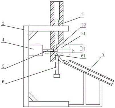
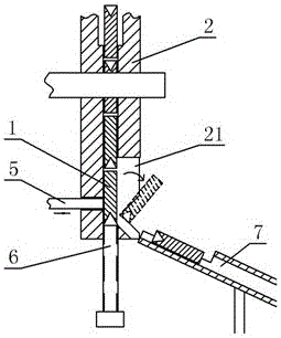
[0021] Such as figure 2 The shown ceramic ferrule direction adjustment mechanism includes a feeding pipe 2, a bracket 3, a cylinder 4, a push rod 5, a tip 6, and a feeding pipe 7.

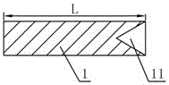
[0022] The feeding pipe 2 is fixed on the upper part of the bracket 3, the feeding pipe 2 is vertically arranged, and there is a vertical pipe inside which the ceramic ferrule can pass through, and a plurality of ceramic ferrules can move along the pipeline in the feeding pipe 2 under the action of gravity. The bottom slides down, and the lower side wall of the feed pipe 2 has a discharge gap 21. The lower end of the feed pipe 2 is threaded to fix the tip 6, the tip 61 is upward and is located in the inner pipeline of the feed tube 2, and the tip 61 is facing the discharge gap 21, and the tip 61 can be inserted into the bottom of the bell mouth 11.

[0023] In order to ensure that the discharge gap 21 can only turn over one ceramic ferrule at a time, the distance H between the upper edge of the d...

Embodiment 2

[0032] Such as Figure 5 , Figure 6 The shown ceramic ferrule direction adjustment mechanism includes a feeding pipe 2, a bracket 3, a motor 8, a runner 9, a tip 6, and a feeding pipe 7.

[0033] Wherein, the structures of the bracket 3, the tip 6, and the material receiving pipe 7 are the same as those in the first embodiment.

[0034] The motor 8 is fixed to the support, and the rotating shaft of the motor 8 is fixed with a runner 9, and the runner 9 has a plurality of gear teeth 91 distributed in an array.

[0035] In order not to damage the ceramic ferrule when colliding, there is a transition arc between at least one outer edge of the gear tooth 91 and the outer edge of other parts of the runner 9, that is, when the runner 9 contacts the ceramic ferrule, the ceramic ferrule moves along the The smooth arc gradually touches the highest point of the gear teeth 91, such as Figure 6 shown.

[0036] There is a fan-shaped channel 23 on the side wall of the feed pipe 2, and...


PUM


Abstract

The invention discloses a direction adjusting mechanism for ceramic insertion cores. The direction adjusting mechanism comprises a support, a feeding pipe, a receiving pipe, a collision body and a driving device. The feeding pipe, the receiving pipe and the driving device are fixed onto the support; a vertical pipeline is arranged inside the feeding pipe, an apex is fixed to the lower end of the feeding pipe, the upward tip of the apex is positioned in the pipeline inside the feeding pipe, a discharge notch is formed in a side wall of the lower portion of the feeding pipe, the tip of the apex directly faces the discharge notch, the distance from the upper edge of the discharge notch to the tip of the apex is larger than the length of each ceramic insertion core but is smaller than 1.5 times the length of each ceramic insertion core, a channel is further arranged on the side wall, which is opposite to the discharge notch, of the feeding pipe, and the distance from the upper edge of the channel to the tip of the apex is smaller than 0,5 times the length of each ceramic insertion core; the receiving pipe is obliquely arranged, and a pipe orifice at the upper end of the receiving pipe is butted to the discharge notch; the driving device is connected with the collision body, the collision body is inserted into the channel on the side wall of the lower portion of the feeding pipe, the driving device can drive the collision body to reciprocate, and the collision body can convexly extend into the pipeline of the feeding pipe when moving.

Description

technical field [0001] The invention relates to a mechanism for adjusting the direction of a ceramic ferrule. Background technique [0002] The ceramic ferrule is the core component of the optical fiber connector. The ceramic ferrule is characterized by smooth outer circle, light weight and large quantity. After the ceramic ferrule is formed, it needs post-processing. For example, it needs to process the bell mouth at one end and chamfer at both ends. Since a large number of ceramic ferrules need to be loaded into the tooling in the same direction during the subsequent grinding process, it is necessary to Before processing, judge, adjust and arrange the head and tail directions of the ceramic ferrules. The existing direction discrimination method generally uses a cylinder to push one end of the ferrule close to the probe. The stroke of the cylinder is fixed, and the bell mouth has a depth, so the ceramic ferrule pushes the probe to move a short distance. The sensor judges t...

Claims


Application Information

Patent Timeline
Patent Type & Authority Patents(China)
IPC IPC(8): B65G47/248
Inventor 李宁航杨武
Owner NINGBO YUNSHENG BONDED MAGNET CO LTD
Why Eureka
Try Eureka