Method for adjusting a rotation angle position of a coil frame and textile machines for producing coils

A creel and rotation angle technology, which is applied in the directions of transportation and packaging, thin material handling, and conveying filamentous materials, etc., can solve the problem of inability to accurately inspect the creel, and achieve the effect of easy visual inspection.

Active Publication Date: 2014-12-24
SAURER SPINNING SOLUTIONS GMBH & CO KG
View PDF9 Cites 4 Cited by
  • Summary
  • Abstract
  • Description
  • Claims
  • Application Information

AI Technical Summary

Problems solved by technology

A more precise check of the actual position of the creel cannot be done here

Method used


Image

  • Method for adjusting a rotation angle position of a coil frame and textile machines for producing coils

Examples


Embodiment Construction

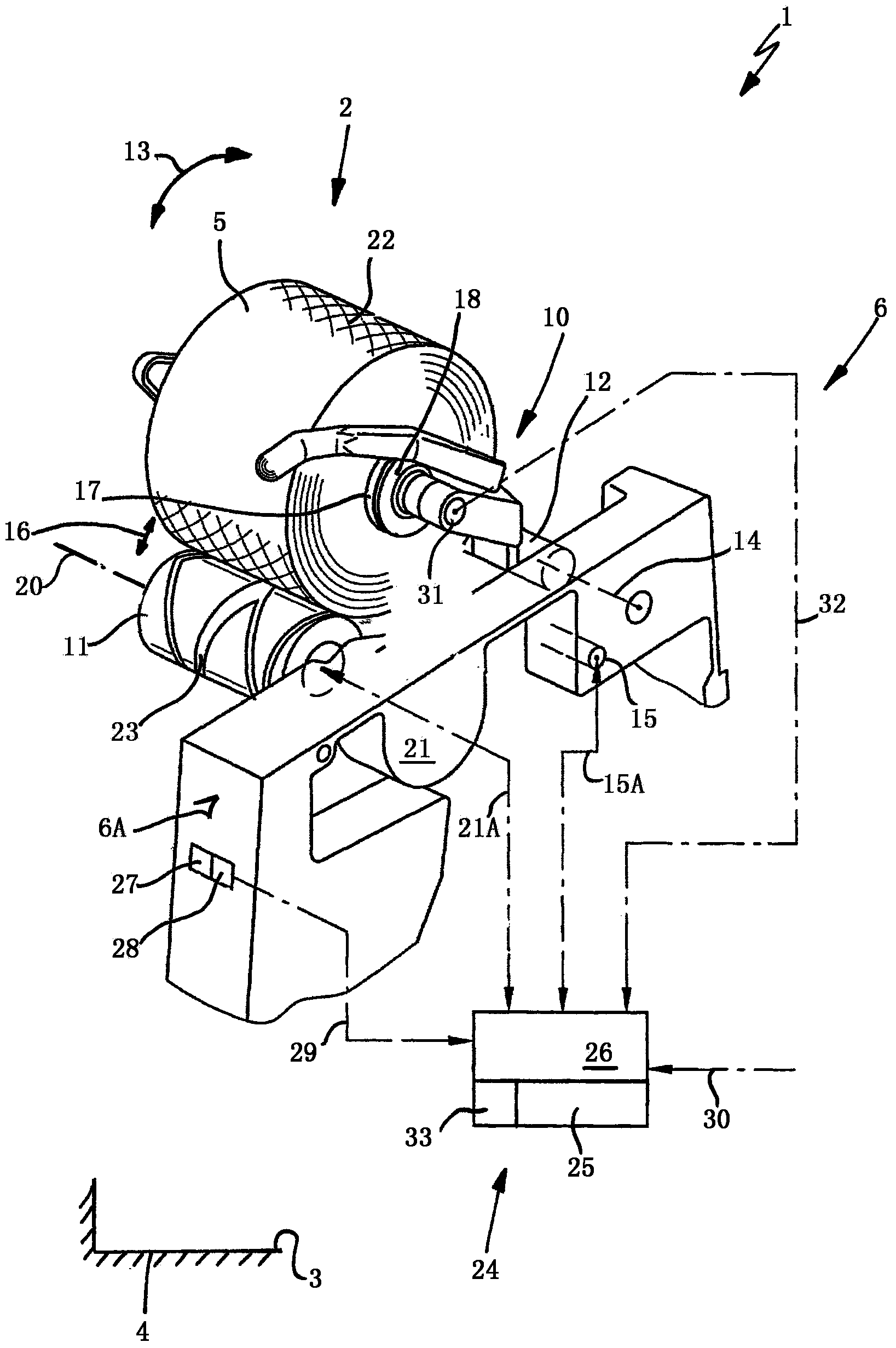
[0099] In this single figure, a winder 1 in a textile machine 3 for producing bobbins 2 is shown schematically, which has a plurality of such winders 1 in it.

[0100] The textile machine 3 for producing bobbins 2 shown in this embodiment is in particular a winding machine 4 for producing cross-wound bobbins 5 .

[0101] Each winding head 1 comprises a support frame 6 on which a creel 10 and a drive roller 11 are mounted.

[0102] For this purpose, a creel 10 is pivotably mounted on the support frame 6 about a pivot axis 14 according to the direction of rotation 13 by means of a swivel mount 12 in the form of a mount shaft and can be driven by a stepper motor 15 . In this respect, the creel 10 driven by the motor can be moved towards or placed on the drive roller 11 or moved or lifted away from the drive roller 11 . Here, the creel 10 must be adjustable relative to the drive roller 11 according to the bobbin diameter which also increases during the bobbin stroke.

[0103] In...


PUM


Abstract

The invention relates to a method for adjusting a rotation angle position of a coil frame and textile machines for producing coils. In the method for adjusting the rotation angle position of the coil frame (10) at a winding head (1), relative to a drive roller (11) for driving a bobbin (17), of the textile machines (3, 4) for producing the coils (2, 5), the coil frame can retain the bobbin in a rotatable movement manner, wherein, at the position of the winding head (1), relative to the drive roller (11), the desired rotation angle basic position of the coil frame (10) is adjusted through the following steps of determining an actual distance between the bobbin retained in the coil frame (10) located at a zero position and a measuring position, and detecting, at the measuring position, operation contact beginning between the bobbin and the drive roller; and determining a correction valve when a difference exists between the determined actual distance and the predetermined desired distance between the bobbin (17) and the drive roller (11), wherein the determined correction valve can be used for a subsequent winding process.

Description

technical field [0001] The invention relates in one aspect to a method for adjusting the angular position of rotation of a creel at the winding head of a textile machine producing bobbins relative to a drive roller for driving bobbins, the creel holding said creel in a rotationally movable manner. bobbin. [0002] In another aspect, the invention relates to a textile machine for producing bobbins, having a plurality of winding heads each comprising: a creel holding bobbins in a rotatably movable manner; drive rollers, The driving roller is used to drive the bobbin; and the driving device is used to adjust the rotational angular position of the creel. Background technique [0003] It is known from the prior art to adjust the creel creel at the winding head of a textile machine producing bobbins rotatably relative to a drive roller etc., so that in particular during the bobbin travel of the bobbin the creel can always be adjusted in a corresponding rotational angular position...

Claims


Application Information

Patent Timeline
Patent Type & Authority Applications(China)
IPC IPC(8): B65H54/54
CPCB65H54/38B65H54/52B65H54/553B65H2701/31
Inventor 弗朗茨-约瑟夫·弗拉姆M·蒙德迈克尔·赖曼
Owner SAURER SPINNING SOLUTIONS GMBH & CO KG
Why Eureka
Try Eureka