Door lock inserting prevention structure

An anti-insertion and door lock technology, which is applied in building locks, building structures, buildings, etc., can solve the problems of unreliable anti-insertion effect and complex structure, and achieve the effect of simple structure and reasonable design.

Active Publication Date: 2014-12-24
四川王力安防产品有限公司
View PDF6 Cites 6 Cited by
  • Summary
  • Abstract
  • Description
  • Claims
  • Application Information

AI Technical Summary

Problems solved by technology

[0007] What the present invention aims to solve is the technical problem of unreliable anti-insertion effect, complex structure, high precision requirements for parts installation and size in the existing door lock anti-insertion structure, so as to provide a reasonable structure, safety for parts and size A door lock anti-insertion structure with low precision requirements, reliable anti-insertion effect and long service life

Method used


Image

  • Door lock inserting prevention structure
  • Door lock inserting prevention structure
  • Door lock inserting prevention structure

Examples


Embodiment 1

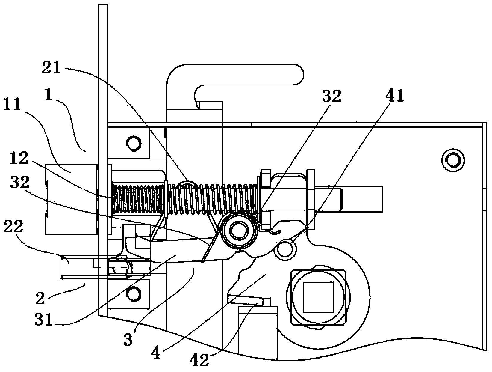
[0043] see Figure 1 to Figure 5 , an anti-insertion structure for a door lock, comprising: a bolt assembly 1 installed in a lock housing, the bolt assembly 1 includes a bolt 11 and a first deflector that makes the bolt 11 move toward the locking direction. Pressing piece 12, the latch bolt 11 can perform the reciprocating movement of locking out and retracting. The latch bolt 11 has an inclined surface facing the door panel. When the door is closed, the latch bolt 11 returns to the lock housing under the extrusion of the door panel. At this time, the latch tongue 11 is also subjected to the first biasing force of the first biasing member 12 towards the lock-out direction. Lock out under the action of a biasing force.

[0044] It also includes an anti-insertion tongue assembly 2, which is installed in the lock housing, see figure 1 , Figure 8 , which includes an anti-insertion tongue 22, and a second biasing member 21 that makes the anti-insertion tongue move toward the lo...

Embodiment 2

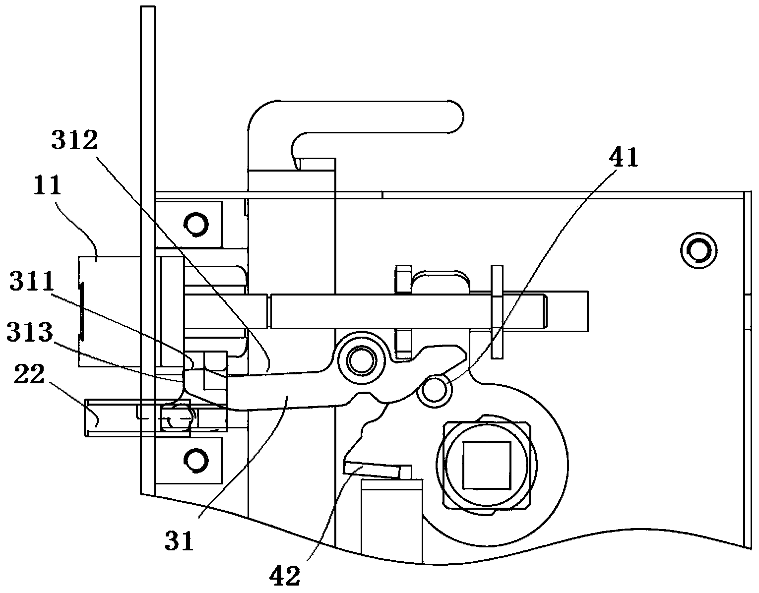
[0069] The difference between this embodiment and embodiment 1 is that, see Figure 9 , 10 , the anti-insertion swing bar 31 is in the shape of an "S", and the paddle assembly 4 also includes a second paddle 43 in the shape of a "6" that rotates together with the handle shaft or the lock cylinder. Next, the handle 431 of the second dial 43 is in contact with the end 313 of the anti-insertion lever 31, so that when the lock is unlocked, the rotation of the second dial 43 drives the anti-insertion lever 31 to release. Rotate against the opposing direction of the latch.

Embodiment 3

[0071] This embodiment is a deformation on the basis of embodiment 1 or embodiment 2, and the difference with embodiment 1 or 2 is:

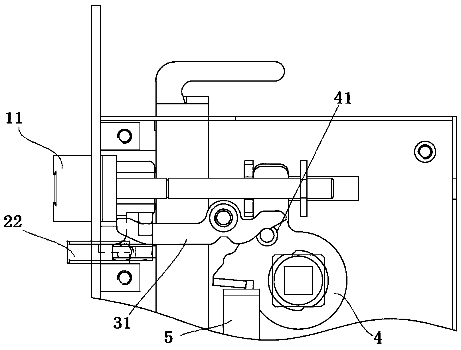
[0072] In this example, see Figure 1-5 , also includes when the key is used to unlock, the key drives the lock cylinder to rotate to drive its linear motion push rod 5, and the push rod 5 drives the paddle assembly 4 to rotate in the unlocking direction during the linear motion, thereby pushing the anti-lock The insertion swing lever 31 turns from the position against the oblique tongue 11 to the anti-insertion tongue position, and the unlocking pin 41 on the first paddle pushes the rear end of the insertion prevention swing lever 31 during the rotation process so that the insertion prevention swing lever 31 Rotate toward the direction of the anti-insertion tongue 22, so that the anti-insertion swing bar 31 is disengaged from the rear end surface of the oblique tongue 11, and the anti-insertion effect is released at this moment, and the door ca...


PUM


Abstract

The invention relates to a door lock inserting prevention structure. A position limiting structure is respectively in contact with a higher-stage step surface and a lower-stage step surface in the process of performing to-and-fro movement along with an inserting prevention bolt in a lock-out direction or a retraction direction, i.e., the position limiting structure respectively acts on the higher-stage step surface and the lower-stage step surface, so that the end parts of an inserting prevention swinging rod are respectively positioned at two different heights, when the position limiting structure acts on the lower-stage step surface, and the front end of the inserting prevention swinging rod is butted against the back end of an inclined bolt, so that the inclined bolt cannot backwards retract, and an inserting prevention effect is achieved. Compared with the prior art in which the design mode that the swinging height of the inserting prevention swinging rod is limited through rotating a bent rod arranged on the inserting prevention bolt in a fixed interval in the process of retracting along with the inserting prevention bolt is adopted, the door lock inserting prevention structure adopts the design mode of acting the position limiting structure onto the higher-stage step surface and the lower-stage step surface of the inserting prevention swinging rod through displacement, and has the advantages that the structure is simple, the design is reasonable, and in addition, stability and reliability are realized.

Description

technical field [0001] The invention relates to an anti-insertion structure of a door lock, which belongs to the field of mechanical locks. Background technique [0002] Generally used door locks, in order to automatically lock when the door is closed, the lock tongue generally adopts the oblique bolt facing the direction of closing the door. Under the locked state, the door lock can be opened by pushing the oblique bolt by inserting thinner items such as cardboard and cards into the door gap. Therefore, this kind of door lock has poor anti-theft performance and has potential safety hazards. [0003] In view of this problem, Chinese patent document CN202483259U discloses a kind of anti-insertion and solution anti-insertion device of lock cylinder, comprises oblique tongue assembly, push plate, spring, anti-insertion plate, anti-insertion driving plate, anti-insertion tongue (6), dial Moving plate, lock body shell; oblique bolt assembly, spring, anti-insertion plate, anti-in...

Claims


Application Information

Patent Timeline
Patent Type & Authority Applications(China)
IPC IPC(8): E05B63/14E05B17/20E05B15/10E05B15/00
Inventor 吕策余开军
Owner 四川王力安防产品有限公司
Why Eureka
Try Eureka