Pump

A pump chamber and suction valve technology, applied in the field of pumps, can solve the problems of difficulty in increasing the compression ratio, thickening of the top panel 105, and complicated assembly procedures, so as to reduce the useless space, reduce the pump pressure head, and improve the The effect of pressure reduction

Active Publication Date: 2014-12-24
ULVAC KIKO
View PDF9 Cites 2 Cited by
  • Summary
  • Abstract
  • Description
  • Claims
  • Application Information

AI Technical Summary

Problems solved by technology

[0009] In the prior art having such a structure, an air intake valve 111 and an air intake valve pressing part 112 are provided on the suction side part of the top panel 105, such as Figure 11 As shown in (a), in order to avoid contact between the piston part 103 and the suction valve holding member 112 when the piston part 103 is at the top dead center, the top plate 105 is spot-faced, and the suction valve 111 and the suction valve holding member are arranged. 112, and use screws 113 to fasten the suction valve 111, so the top plate 105 becomes thicker, and there is an extra space for the exhaust port 120, so there is an extra space (useless space) in the pump chamber 102, and it is difficult to increase the pressure. scaling problem
[0010] Moreover, in the prior art, since the suction valve pressing member 112, the exhaust valve pressing member 122, and the screws 113, 123 are required respectively, the number of parts is large, and the assembly process is complicated due to screw fastening and the like. , so there is a problem that causes the cost to increase

Method used


Image

  • Pump
  • Pump
  • Pump

Examples


Embodiment Construction

[0037] Hereinafter, embodiments of the present invention will be described in detail with reference to the drawings.

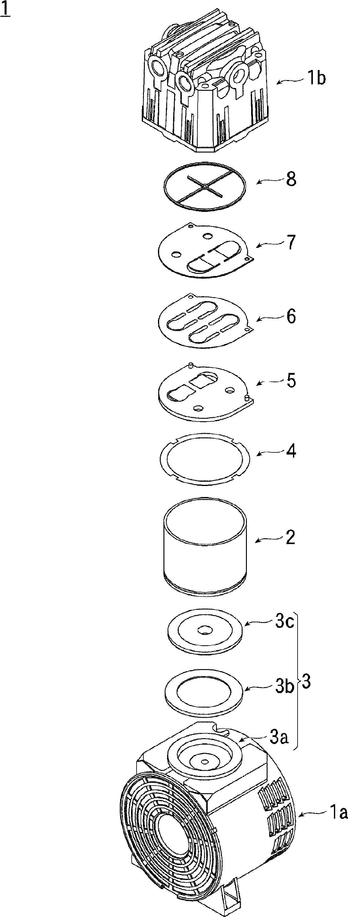
[0038] figure 1 It is an exploded perspective view showing the configuration of main parts of an embodiment of the pump according to the present invention.

[0039] Such as figure 1 As shown, the pump 1 of the present embodiment is provided with a top cover 1b on an upper portion of a drive unit 1a (the driving source is omitted in the figure), and the following components are arranged inside the top cover 1b.

[0040] A pump chamber 2 is provided on the upper part of the driving part 1a, and a piston part 3 reciprocatingly moved by an eccentric shaft fastened to a motor (not shown) is inserted into the pump chamber 2 .

[0041] The piston part 3 is constituted by screwing a cup seal 3b and a cup seal hold-down plate 3c, which perform a sealing function while sliding, to a connecting rod 3a.

[0042] On the other hand, a top plate 5 is attached to an uppe...


PUM


Abstract

The invention provides a pump which is provided with a suction/exhaust valve that is composed of reed valves. Compression ratio can be improved through reducing a useless space in a pump chamber. Simultaneously number reduction of elements and assembling process simplification can be realized. An exhaust side surface (50a) of a body part (50) of a top panel (5) arranged at the upper part of a pump chamber (2) is provided with a recessed suction valve compressing part (52). The suction valve compressing part (52) inclines in a manner that the thickness reduces in a direction to a suction port (51) and is continuous with the suction port (51). The pump is provided with a suction/exhaust valve component (6) which is provided with a panel-shaped body part (60) that is positioned and configured in a manner of closely abutting with the exhausting side relative to the top panel (5). The pump is furthermore provided with a suction valve (62) which is arranged integrally with the body part (60) of the suction/exhaust valve component (6) in a manner of superposing with the suction port (51) of the top panel (5) and the suction valve compressing part (52).

Description

technical field [0001] The present invention relates to pumps having reed valves (valve constructed from cantilevered beams), and more particularly to the construction of the spool boot for limiting the amount of lift of the valve. Background technique [0002] Conventionally, as a pump having a reed valve, there is known a pump in which the movement of the intake and exhaust valves is suppressed by a pressing member in order to improve durability and reduce noise by limiting the lift of the valve. [0003] Figure 10 It is an exploded perspective view showing the structure of main parts of a conventional pump 101, Figure 11 (a), Figure 11 (b) is a sectional view showing a valve structure of a conventional pump, Figure 11 (a) is the case where the piston part is at the top dead center position, Figure 11 (b) is a case where the piston part is at the bottom dead center position. [0004] Such as Figure 10 As shown, in such a pump 101 , for example, a pump chamber 102...

Claims


Application Information

Patent Timeline
Patent Type & Authority Applications(China)
IPC IPC(8): F04B39/10
CPCF04B39/1073F04B39/12F05B2210/12F05B2260/60Y10S417/00
Inventor 大坂泰介田边优作
Owner ULVAC KIKO
Why Eureka
Try Eureka