Flat band bonding machine

A bonding machine and flat belt technology, applied in mechanical equipment, connecting components, etc., can solve problems such as low production efficiency, deviation, and large transmission energy loss, so as to make up for the vacancy of production equipment and strengthen the bonding fastness , the effect of meeting the needs of the market

Inactive Publication Date: 2014-12-24
苏州震昇机电设备有限公司
View PDF6 Cites 1 Cited by
  • Summary
  • Abstract
  • Description
  • Claims
  • Application Information

AI Technical Summary

Problems solved by technology

[0002] When the automated logistics company receives the goods for unloading, it generally needs to load and unload the goods through automated transmission components. The original transmission uses round belts to realize the transmission of the upper and lower structures of the logistics, but the use of this round belt The upper and lower structure automatic logistics transmission process often deviates, so it needs to be equipped with round pulleys, and the driven roller must be grooved. Such a structure is inconvenient to install, the transmission energy consumption is large, and it also increases the economic expenditure. To meet the needs of the rapid development of automated logistics projects at home and abroad, a flat belt transmission belt has been developed. The existing processing and production methods of this flat belt transmission belt are generally manual processing, and the production efficiency of its products is low and the operation is complicated. It is cumbersome, and the bonding fastness of the product is not strong, which cannot meet the needs of automated logistics production

Method used


Image

  • Flat band bonding machine
  • Flat band bonding machine
  • Flat band bonding machine

Examples


Embodiment Construction

[0016] The present invention is described below in conjunction with accompanying drawing.

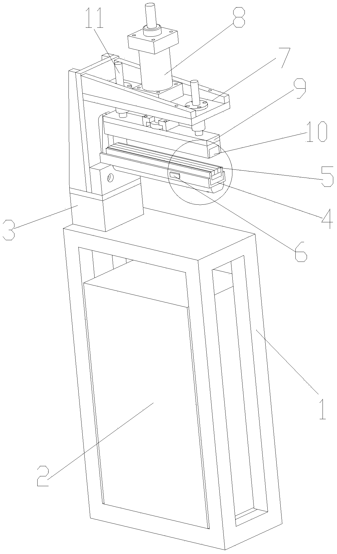
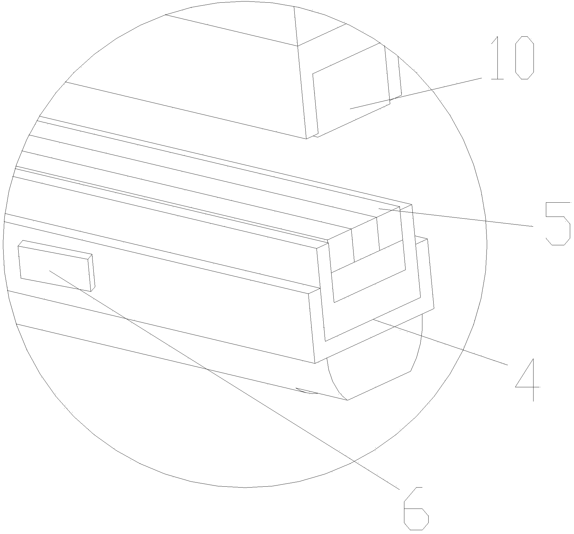
[0017] as attached Figure 1-5 The shown flat belt bonding machine of the present invention includes a frame 1, a control system 2, a support frame 3, a lower bezel 4, a heating plate 5, a temperature sensor 6, a fixing plate 7, a cylinder 8, an upper bead 9 and iron sheet 10; the frame 1 is provided with a control system 2; one side of the top of the frame 1 is provided with a support frame 3; the middle part of the support frame 3 has a groove; The lower bezel 4 is fixed; the lower bead 4 is provided with a plurality of heating plates 5; one side of the lower bead 4 is also provided with a temperature sensor 6; the support frame 3 is provided with a fixed plate 7; the fixed plate 7 is provided with a cylinder 8; the telescopic rod of the cylinder 8 is provided with an upper bead 9; the upper bead 9 is located between the fixed plate 7 and the lower bead 4; an iron sheet 10 is provide...


PUM


Abstract

The invention discloses a flat band bonding machine. The flat band bonding machine comprises a rack, a control system, a supporting frame, a lower pressing strip, heating sheets, a temperature sensor, a fixed plate, an air cylinder, an upper pressing strip and an iron sheet, wherein the control system is arranged in the rack; the supporting frame is arranged on one side of the top of the rack; a groove is formed in the middle part of the supporting frame; the lower pressing strip is longitudinally fixed on the groove; a plurality of heating sheets are arranged on the lower pressing strip; the temperature sensor is additionally arranged on one side of the lower pressing strip; the fixed plate is arranged above the supporting frame; the air cylinder is arranged on the fixed plate; the upper pressing strip is arranged below a telescopic rod of the air cylinder; the upper strip is located between the fixed plate and the lower pressing strip; the iron sheet is arranged below the upper pressing strip; the temperature sensor, the air cylinder and the heating sheets are respectively connected with the control system. The flat band bonding machine disclosed by the invention has the advantages that the production efficiency is high, the operation is simple, the blank of polyurethane flat band production equipment in the market is filled, the bonding firmness is high, the market demands are well satisfied and the flat band bonding machine is suitable for being widely popularized and used.

Description

technical field [0001] The invention relates to a flat belt bonding machine, in particular to a flat belt bonding machine for polyurethane. Background technique [0002] When the automated logistics company receives the goods for unloading, it generally needs to load and unload the goods through automated transmission components. The original transmission uses round belts to realize the transmission of the upper and lower structures of the logistics, but the use of this round belt The upper and lower structure automatic logistics transmission process often deviates, so it needs to be equipped with round pulleys, and the driven roller must be grooved. Such a structure is inconvenient to install, the transmission energy consumption is large, and it also increases the economic expenditure. To meet the needs of the rapid development of automated logistics projects at home and abroad, a flat belt transmission belt has been developed. The existing processing and production methods...

Claims


Application Information

Patent Timeline
Patent Type & Authority Applications(China)
IPC IPC(8): F16B11/00
Inventor 徐智清
Owner 苏州震昇机电设备有限公司
Why Eureka
Try Eureka