
Leaky-wave antenna for feeding of quasi-surface plasma polariton transmission line

A surface plasmon and leaky wave antenna technology, applied in the wireless field, can solve the problems of blank, millimeter wave antenna and millimeter wave device research are very few, and achieve the effects of easy processing, novel design and good development prospects

Inactive Publication Date: 2017-12-12
BEIJING JIAOTONG UNIV
View PDF2 Cites 3 Cited by
  • Summary
  • Abstract
  • Description
  • Claims
  • Application Information

AI Technical Summary

Problems solved by technology

[0003] At present, the research on surface plasmons at home and abroad mostly stays on the transfer structure from the traditional waveguide structure to the surface plasmon transmission line, and the millimeter wave antenna and other Research on millimeter wave devices is very little, almost blank

Method used


Image

  • Leaky-wave antenna for feeding of quasi-surface plasma polariton transmission line
  • Leaky-wave antenna for feeding of quasi-surface plasma polariton transmission line
  • Leaky-wave antenna for feeding of quasi-surface plasma polariton transmission line

Examples


Embodiment

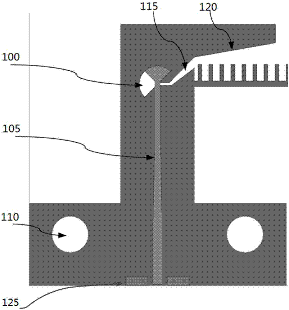
[0049] Such as figure 1 Shown is a top view of the structural components in the transition structure in the embodiment of the present invention. The transfer structure includes two structural parts, which are symmetrically arranged at both ends of the dielectric board, wherein each structural part includes a microstrip line 105 on the upper surface of the dielectric board, and an inverted groove line 100 on the lower surface of the dielectric board. T-shaped metal layer.

[0050] The top of the groove line 100 is a 1 / 4 fan-shaped radius of 1mm, and the end gradually opens obliquely upwards. The inclination angle of the lower side is 37°, and the length is 1.95mm. The inclination angle of the upper side is 46°, and the length is 1.45mm. The opening 115 is 0.6 mm. The purpose of the extended protrusion 120 is to help confine the energy in the groove structure of the surface plasmon, the inclination angle is 10°, and the length is 4.5mm.

[0051] The microstrip line 105 consis...


PUM


Abstract

The invention discloses a leaky-wave antenna for feeding of a quasi-surface plasma polariton transmission line. The leaky-wave antenna comprises a dielectric plate, a connection structure, grounding structures, a transmission line and an annular antenna array, wherein the connection structure comprises two member pieces which are symmetrically arranged at two ends of the dielectric plate, the grounding structures are arranged on the two structural members in the connection structure and penetrate through the dielectric plates at corresponding positions, two ends of the transmission line are respectively connected with two metal layers containing groove lines in the connection structure and are arranged on a first surface of the dielectric plate, and the annular antenna array is formed by periodically arranging a plurality of metal rings and are maintained with the transmission line at interval.

Description

technical field [0001] The present invention relates to the field of wireless technology. More specifically, it relates to a leaky-wave antenna fed by a quasi-surface plasmon transmission line. Background technique [0002] The surface plasmon polariton structure has the characteristics of breaking through the diffraction limit, enhancing electromagnetic wave transmission, and confining energy in sub-wavelength size structures. The transmission line based on surface plasmon polaritons and the antenna fed by the above-mentioned transmission line have a simple structure, are easy to integrate, and have excellent performance, showing great advantages in the millimeter wave and terahertz frequency bands. [0003] At present, the research on surface plasmons at home and abroad mostly stays on the transfer structure from the traditional guided wave structure to the surface plasmon transmission line, and the millimeter-wave antenna and other Research on millimeter wave devices is...

Claims


Application Information

Patent Timeline
Patent Type & Authority Applications(China)
IPC IPC(8): H01Q1/38H01Q1/50H01Q7/00
CPCH01Q1/38H01Q1/50H01Q7/00
Inventor 李雨键曹迪王均宏张展陈美娥李铮
Owner BEIJING JIAOTONG UNIV
Learn More