Hydraulic mount

A hydraulic mount and housing technology, applied in the direction of springs, shock absorbers, spring/shock absorbers, etc., can solve the problems of reducing high-frequency dynamic stiffness, failure to reach, and easy to fall off, so as to increase stability and prevent The effect of overall cracking, reducing abnormal noise or interference

Active Publication Date: 2014-12-24
ANHUI JIANGHUAI AUTOMOBILE GRP CORP LTD
View PDF7 Cites 7 Cited by
  • Summary
  • Abstract
  • Description
  • Claims
  • Application Information

AI Technical Summary

Problems solved by technology

[0008] (1) The internal space layout is limited, and the design of the rubber main spring needs to consider avoiding the spoiler, and sometimes sacrifices in durability and other performance;
[0009] (2) There are risks in reliability, and problems such as falling off and abnormal noise due to movement interference are prone to occur;
[0010] (3) The cost is high, including material purchase cost, mold cost and assembly cost of the production line
However, although this solution reduces the high-frequency dynamic stiffness to a certain extent, it does not achieve the effect of installing a spoiler

Method used


Image

  • Hydraulic mount
  • Hydraulic mount
  • Hydraulic mount

Examples


Embodiment Construction

[0062] In order to make the above objects, features and advantages of the present invention more comprehensible, specific implementations of the present invention will be described in detail below in conjunction with the accompanying drawings.

[0063] In the following description, a lot of specific details are set forth in order to fully understand the present invention, but the present invention can also be implemented in other ways different from those described here, and those skilled in the art can do it without departing from the meaning of the present invention. By analogy, the present invention is therefore not limited to the specific examples disclosed below.

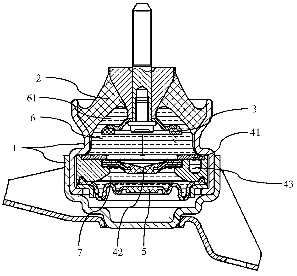
[0064] refer to Figure 5 to Figure 8 As shown, a hydraulic mount has an outer casing, a main shock absorber, a separator and a bottom sealing body.

[0065] The outer casing includes an upper casing 13 and a lower casing 14 .

[0066] The upper casing 13 and the lower casing 14 are sealed by wrapping. In thi...


PUM


Abstract

The invention provides a hydraulic mount, which is provided with an outer shell, a main vibration attenuation body, a separation body and a bottom sealing body, wherein the separation body comprises a low-frequency runner and a high-frequency diaphragm, and the low-frequency runner and the high-frequency diaphragm are vulcanized into a whole; the low-frequency runner is provided with a turbulent flow flange; the high-frequency diaphragm is provided with a notch. According to the low-frequency runner and the high-frequency diaphragm which are integrally vulcanized, the stability of suspension work is improved, the turbulent flow flange replaces a turbulent flow plate so as to reduce abnormal sound or interference caused by the reason that the bolts of the turbulent flow plate loose or fall under vibration, the high-pressure diaphragm is provided with a notch to lower dynamic stiffness under high frequency, an aerial drainage function is formed when the hydraulic mount is under large pressure, and the high-frequency diaphragm is prevented from integrally breaking.

Description

technical field [0001] The invention relates to the technical field of automobile engine mounts, in particular to a hydraulic mount. Background technique [0002] For the engine side mount, in order to improve its vibration isolation performance at high frequencies, it is generally designed as a hydraulic mount. The main performance parameters of the hydraulic mount include the dynamic-to-static ratio and the dynamic stiffness at high frequencies. [0003] Static stiffness refers to the amount of deformation produced by an object under a certain external force; dynamic stiffness is the definition relative to static stiffness, and dynamic stiffness is the amount of deformation produced by an object under the action of an external force at a certain frequency; the dynamic-static ratio is the dynamic stiffness and static stiffness ratio. [0004] Such as figure 1 , figure 2 , image 3 As shown in FIG. 1 , it is a schematic diagram of the structure of the hydraulic mount in...

Claims


Application Information

Patent Timeline
Patent Type & Authority Applications(China)
IPC IPC(8): F16F9/32
Inventor 彭宜爱王方张家彬刘子萌
Owner ANHUI JIANGHUAI AUTOMOBILE GRP CORP LTD
Why Eureka
Try Eureka