A secondary combustion system

A secondary combustion and burner technology, which is applied in the direction of combustion method, combustion type, lighting and heating equipment, etc., can solve the problems of insufficient combustion and environmental impact, and achieve complete combustion, good environmental protection, and obvious separation effect Effect

Active Publication Date: 2016-07-06
ZHEJIANG SANLIAN ENVIRONMENT MACHINERY EQUIP
View PDF5 Cites 0 Cited by
  • Summary
  • Abstract
  • Description
  • Claims
  • Application Information

AI Technical Summary

Problems solved by technology

After incineration in the kiln, a large amount of hot flue gas will be produced. These hot flue gases contain a lot of high-temperature volatiles and dust, and due to factors such as insufficient combustion, they contain a large amount of dioxin. Discharged out will cause extremely bad impact on the environment, but there are still many defects in the means of dealing with these problems

Method used


Image

  • A secondary combustion system
  • A secondary combustion system
  • A secondary combustion system

Examples


Embodiment 1

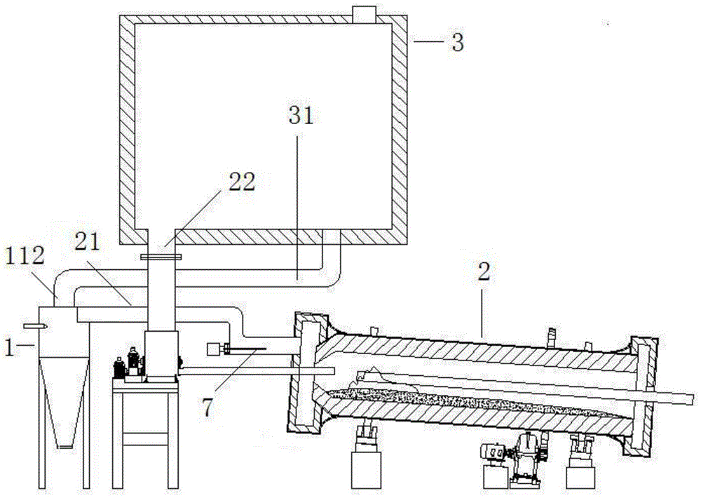
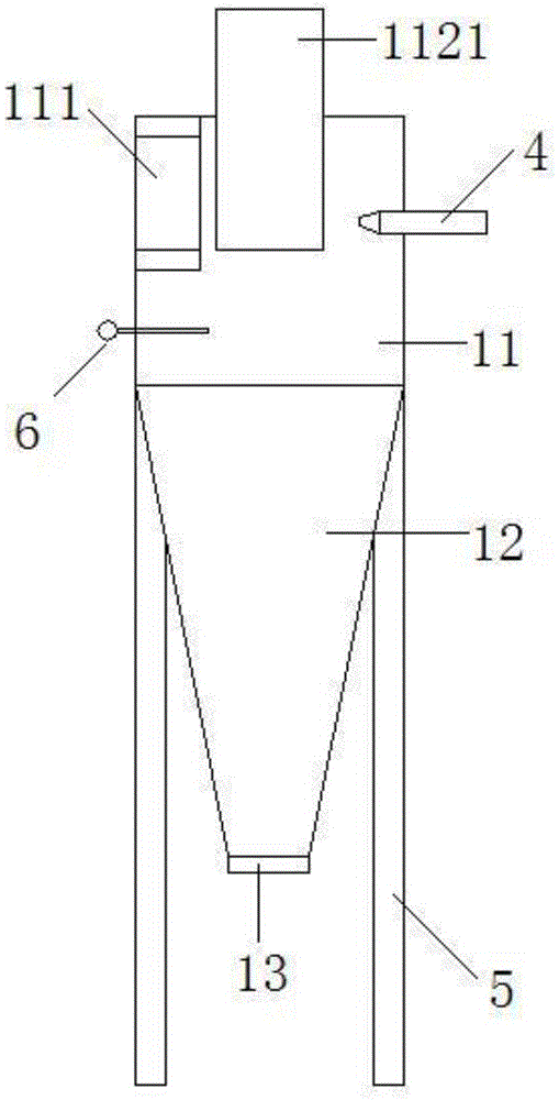
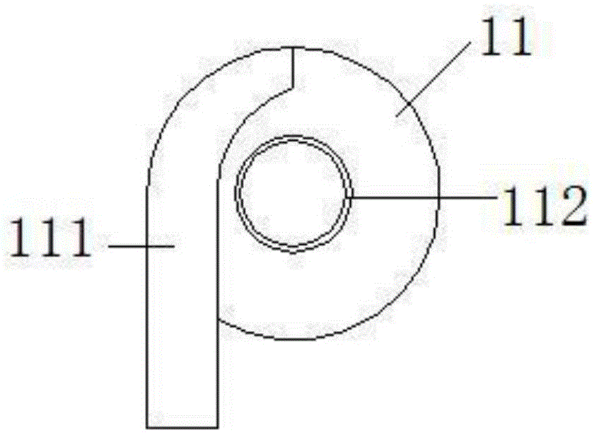
[0020] Embodiment 1: as figure 1 , figure 2 , image 3 , Figure 4 , Figure 5 In the shown embodiment, a secondary combustion system includes a secondary combustion chamber 1, a hot flue gas return pipe 21 communicating with the kiln tail of the rotary kiln 2, and the rotary kiln 2 is connected to the drying chamber through a feed pipe 22. chamber 3, the upper part of the side wall of the second combustion chamber 1 is provided with a smoke inlet 111, and the smoke inlet 111 is connected to the hot flue gas return pipe 21, and the second combustion chamber 1 is provided with a head extending into the second The burner 4 in the combustion chamber 1, the described secondary combustion chamber 1 includes a cylindrical main combustion chamber 11 and a deposition recovery chamber 12 connected below the main combustion chamber 11, the cross-sectional diameter of the deposition recovery chamber 12 is determined by Decreasing from top to bottom, the bottom of the second combusti...

Embodiment 2

[0023] Embodiment 2: the basic structure and implementation mode of this embodiment are the same as embodiment 1, and its difference is, as Figure 6 As shown: the air outlet 31 is provided with a depressurizing part 32 with a diameter larger than that of the air outlet 31, and the air outlet 31 is provided with an air pump 8, and the air pump 8 is located between the drying chamber 3 and the air outlet. Between the pressing parts 32.

[0024] The pressure-reducing part 32 has a relatively large caliber, which can reduce the instantaneous air pressure of the purified hot flue gas after reaching here, so that the airflow can enter smoothly, so that the airflow in the section of the air outlet 31 before the pressure-reducing part 32 can be more smoothly. Supplemented by the suction of the air pump 8, the smooth flow of the air flow in the entire air outlet can be guaranteed, thereby avoiding the air flow block at the air outlet 112, so that the purified hot flue gas can leave t...


PUM


Abstract

The invention discloses a secondary combustion system, which aims to provide a system capable of purifying hot flue gas, fully removing high-temperature volatiles and dioxins, and recovering dust and iron slag conveniently and efficiently. Energy-saving secondary combustion device. It includes a secondary combustion chamber, a hot flue gas return pipe, and the rotary kiln is connected to the drying chamber. The smoke inlet and burner are arranged on the secondary combustion chamber. The secondary combustion chamber includes a main combustion chamber and a deposition recovery chamber. There is a gas outlet, the lower end of the gas outlet extends into the second combustion chamber, the gas outlet is connected to an air outlet, the outlet is connected to the drying room, the direction of the smoke inlet is parallel to the tangential direction outside the main combustion chamber, and the smoke inlet is connected to the The angle between the horizontal planes is 10 to 30 degrees. The beneficial effects of the invention are: the harmful substances can be burned again; the combustion is complete and complete; no additional device is needed and the dust separation effect is obvious; the purified hot flue gas can be recycled again, and the environmental protection is good.

Description

technical field [0001] The invention belongs to the field of sludge treatment, in particular to a secondary combustion system. Background technique [0002] In the process of sewage treatment, a large amount of sludge will be produced, which contains a large amount of organic matter, heavy metals, and microorganisms. Usually, the treatment method for these sludge is landfill or incineration, and landfill requires a large amount of land, and it will affect the quality of the landfill. The land after burial causes serious pollution and serious waste of land resources; incineration treatment is currently the most thorough solution to sludge. Before incineration, the sludge needs to be centrifugally dehydrated and dried, and then further dried in a drying room before being incinerated in a kiln. Generally speaking, the incineration temperature is about 650 degrees. After incineration in the kiln, a large amount of hot flue gas will be produced. These hot flue gases contain a lo...

Claims


Application Information

Patent Timeline
Patent Type & Authority Patents(China)
IPC IPC(8): F23G7/06
Inventor 纪伟勇王艳丽李秀朝张家云项乐群应文勇
Owner ZHEJIANG SANLIAN ENVIRONMENT MACHINERY EQUIP
Why Eureka
Try Eureka