Microwave generating device and microwave high-temperature air pressure device with microwave generating device

A microwave generating device and microwave technology, which is applied in the field of microwave generating devices and microwave high-temperature gas pressure devices, can solve the problems of high heat loss rate, air flow leakage, and difficulty in ensuring the compression resistance of the feed-in part, so as to ensure the gas pressure and internal temperature , the effect of preventing air leakage

Active Publication Date: 2014-12-24
湖南华冶微波科技有限公司
View PDF7 Cites 37 Cited by
  • Summary
  • Abstract
  • Description
  • Claims
  • Application Information

AI Technical Summary

Problems solved by technology

[0003] The object of the present invention is to provide a microwave generating device and a microwave high-temperature pneumatic device with the microwave generating device, to solve the problem that the feed-in structure of the existing microwave device is difficult to ensure the compression resistance of the feed-in part, and it is easy to cause The airflow leaks from the microwave device, which makes the internal pressure continue to drop and the heat loss rate is high. At the same time, the leaked airflow easily impacts the microwave source, resulting in the technical problem of microwave source function failure

Method used


Image

  • Microwave generating device and microwave high-temperature air pressure device with microwave generating device
  • Microwave generating device and microwave high-temperature air pressure device with microwave generating device
  • Microwave generating device and microwave high-temperature air pressure device with microwave generating device

Examples


Embodiment Construction

[0023] The embodiments of the present invention will be described in detail below with reference to the accompanying drawings, but the present invention can be implemented in various ways defined and covered.

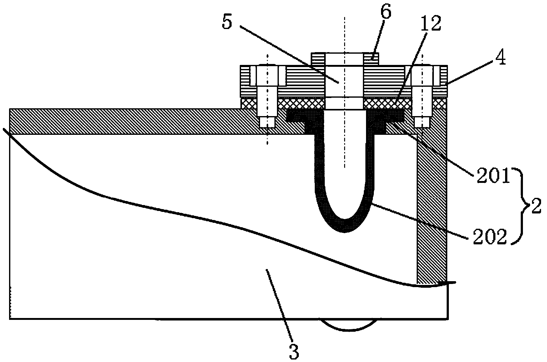
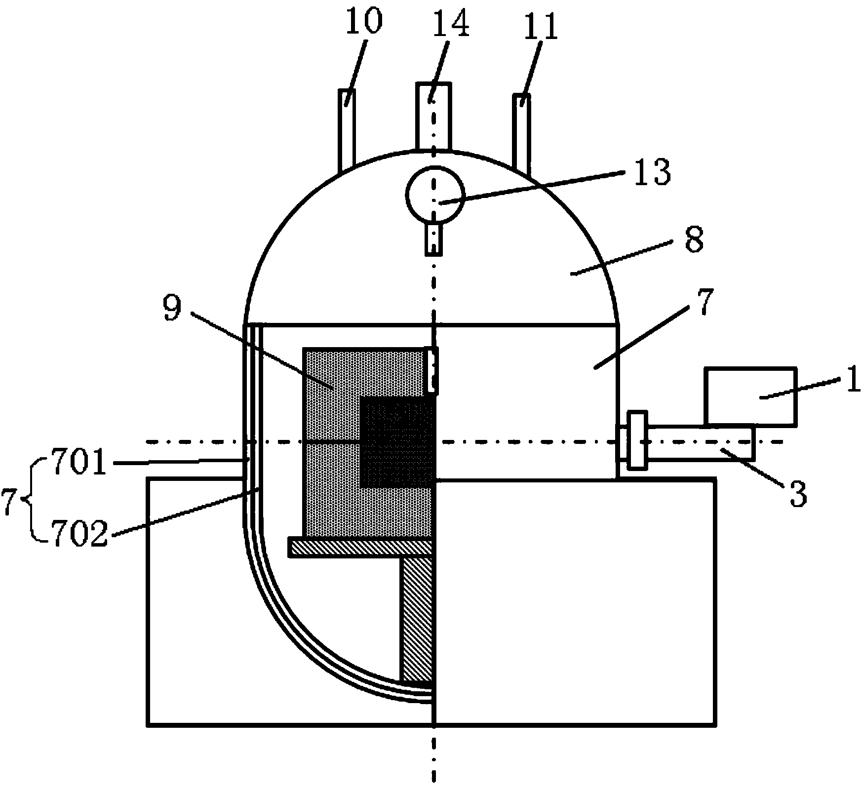
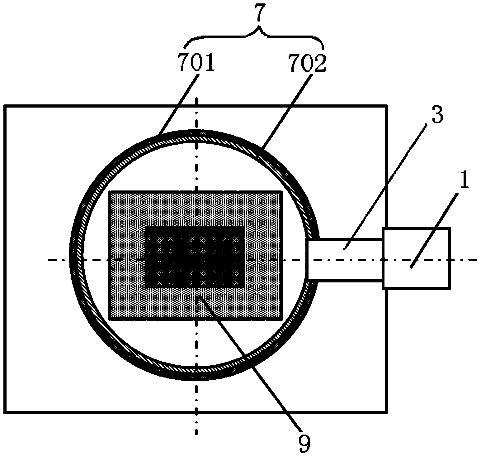
[0024] figure 1 is a schematic structural diagram of a microwave generating device in a preferred embodiment of the present invention; figure 2 It is one of the structural schematic diagrams of the microwave high-temperature pneumatic device with microwave generating device in the preferred embodiment of the present invention; image 3 It is the second schematic diagram of the structure of the microwave high-temperature pneumatic device with microwave generating device in the preferred embodiment of the present invention.

[0025] Such as figure 1 As shown, the microwave generating device of this embodiment includes a microwave source 1 for emitting microwaves, a wave-transparent pressure-resistant part 2 for bearing pressure and transmitting microwaves, and a pressu...


PUM


Abstract

The invention discloses a microwave generating device and a microwave high-temperature air pressure device with the microwave generating device. The microwave generating device comprises a microwave source, a wave transmission pressure-resistant element and a pressure-resistant waveguide, wherein the microwave source is used for giving out microwaves, the wave transmission pressure-resistant element is used for bearing the pressure and transmitting the microwaves, the pressure-resistant waveguide is used for bearing the pressure, transmitting electromagnetic waves and feeding back energy, an energy feedback antenna of the microwave source is arranged in the wave transmission pressure-resistant element, the energy feedback antenna and the wave transmission pressure-resistant element are simultaneously connected into the waveguide, the inner wall surface of the pressure-resistant waveguide defines and forms a microwave resonant cavity so that the microwaves generated by the microwave source can enter the pressure-resistant waveguide through the wave transmission pressure-resistant element, and the resonance is formed in the pressure-resistant waveguide and is transmitted to a target cavity. Through a combined structure of the wave transmission pressure-resistant element and the pressure-resistant waveguide, the pressure resistance in the microwave transmission position is realized, the air pressure outward leakage condition can be effectively prevented, the air pressure and the inside temperature of the target cavity are ensured, and the microwave source function failure caused when airflow enters the microwave source through the pressure-resistant waveguide can be effectively prevented.

Description

technical field [0001] The invention relates to the field of synthesis and decomposition equipment, in particular to a microwave generating device. In addition, the present invention also relates to a microwave high-temperature air pressure device comprising the above-mentioned microwave generating device. Background technique [0002] Microwave air pressure device is a new type of device that microwave energy can be applied to chemical synthesis or decomposition, and material preparation process. It can effectively promote chemical synthesis, solidification, and improve the performance of sintered materials. It has been widely used in digestion technology. At present, there are three main feeding methods and feeding structures of microwave devices: Method 1: adopt the waveguide-blind plate feeding method of conventional microwave devices, and use pressure-resistant test tubes to seal reagents and materials. Method 2: Improve the pressure resistance of the microwave pneumat...

Claims


Application Information

Patent Timeline
Patent Type & Authority Applications(China)
IPC IPC(8): F27B5/00F27B5/14H05B6/64
Inventor 李德华潘慧娟向伯荣李斌
Owner 湖南华冶微波科技有限公司
Why Eureka
Try Eureka