Sensing device based on friction generating technology and preparing and using method of sensing device

A technology of sensing device and friction power generation, which is applied in the direction of friction generator and electric/magnetic device to transmit sensing components, etc., can solve the problems of complex positioning circuit, unfavorable application, low resolution, etc., and achieve simple output signal wiring, The effect of simple manufacturing process and high resolution

Active Publication Date: 2014-12-24
BEIJING INST OF NANOENERGY & NANOSYST
View PDF5 Cites 18 Cited by
  • Summary
  • Abstract
  • Description
  • Claims
  • Application Information

AI Technical Summary

Problems solved by technology

However, the sensors designed based on the existing friction generators have defects such as low resolution and complex positioning circuits, which are not conducive to practical application

Method used


Image

  • Sensing device based on friction generating technology and preparing and using method of sensing device
  • Sensing device based on friction generating technology and preparing and using method of sensing device
  • Sensing device based on friction generating technology and preparing and using method of sensing device

Examples


preparation example Construction

[0093] Another manufacturing method of the sensing device provided by the present invention is more suitable for the case where the first unit 10 and the second unit 20 have opposite upper and lower relative positions at any two adjacent intersection points. Specifically include the following steps:

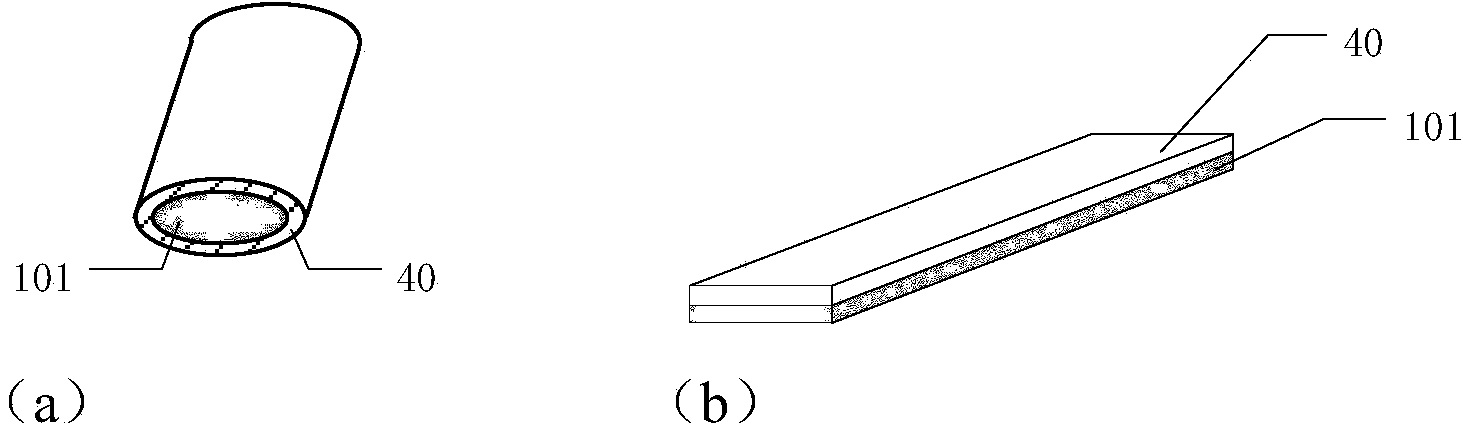
[0094] (1) Provide n+m wires whose interior is a conductor and whose exterior is coated with insulating material, and several electrical signal output terminals with one end grounded;

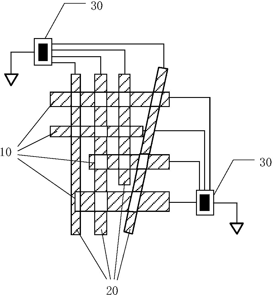
[0095] (2) Using n threads as warps and m threads as wefts, the warps and wefts intersect each other to form a network structure, each warp is a first unit, and each weft is a Second unit;

[0096] (3) The n warp threads and the m weft threads are respectively electrically connected to the electrical signal output terminal through internal conductors, so as to individually monitor the output signal of each unit.

[0097] Wherein the formation of the network structure in step (2) may adopt a conv...

Embodiment 1

[0117] Example 1 θ = arctg v y v x = arctg a y a x - - - ( 7 )

[0118] Prepare a perforated plexiglass with a size of 20cm×20cm as the substrate, spread 9 aluminum strips with a width of 6mm and a length of 20cm in parallel on the x-direction of the substrate surface, and the distance d between adjacent aluminum strips is 14mm, And the lower surface of each aluminum strip passes through 9 uniformly arranged holes on the base, and the part passing through the holes is embedded into the holes by extrusion. Prepare another 9 aluminum strips of the same size and spread them on the surface of the above-mentioned substrate along the y direction in a similar manner, ...

Embodiment 2

[0121] The enameled wire with a diameter of about 120 μm is woven into a mesh structure, the grid spacing is 250 μm, and the number of electrodes in the dimension is 41 on the length of 1 cm. 2 The area of ​​has 41 x output terminals and 41 y output terminals, forming 41×41=1681 pixel resolution, such as Figure 11 (a) shown. When an object with a diameter of 1.2mm slides along the "G" track on the device, the single signal output of its x output and y output is as follows: Figure 11 As shown in (b), the current signal-to-noise ratio reaches 50. Such as Figure 11 (c) is the time-varying relationship of the x-y output current peak signal during the movement of the slider. Its motion trajectory can be clearly seen from the x-y coordinate axis, and its motion speed and acceleration can be calculated through the x-t and y-t relationships.


PUM


Abstract

The invention provides a sensing device based on the friction generating technology and a preparing and using method of the sensing device. A self-driven working mode in which a power source does not need to be additionally arranged and monitoring can be carried out anytime is achieved in the sensing device through the friction generating technology. The sensing device comprises two arrays. Each array is composed of a plurality of independent units which intersect with one another in an insulated mode to form a net structure. An independent sensing pixel point is arranged between every two adjacent intersections. Electrical signals of all the sensing units are independently output. By means of the net structures, the resolution ratio of the sensing device is greatly improved, the wiring number of circuit connection is reduced, and large-scale industrial application is greatly facilitated.

Description

technical field [0001] The invention relates to a sensor device and its preparation and use method, in particular to a sensor device based on triboelectric generation technology and its preparation and use method. Background technique [0002] Tracking sensors are increasingly used in smartphones and body tracking systems, but current sensors are based on capacitance, or optical and magnetic effects. Generally speaking, the power supply of these sensors comes directly or indirectly from the battery. This has caused great hidden dangers of power outages for some situations that need to be on call at any time and signal monitoring from time to time; and in a wide range of applications, a lot of maintenance work is required in terms of battery power monitoring and battery replacement; at the same time, traditional batteries and power supply The large volume and mass of the system limit the application of the sensor in some fields; moreover, the toxic chemical substances contai...

Claims


Application Information

Patent Timeline
Patent Type & Authority Applications(China)
IPC IPC(8): G01D5/12H02N1/04
Inventor 韩昌报王中林李晓慧张弛
Owner BEIJING INST OF NANOENERGY & NANOSYST
Why Eureka
Try Eureka