Vertical dropping impact test system

An impact test and tested technology, applied in the direction of impact test, vibration test, machine/structural component test, etc., can solve the problems of inaccurate test results, unfavorable use, single test function, etc., to prevent equipment damage and personal injury. Injury, cost savings, accurate test results

Active Publication Date: 2014-12-24
HEFEI UNIV OF TECH
View PDF7 Cites 36 Cited by
  • Summary
  • Abstract
  • Description
  • Claims
  • Application Information

AI Technical Summary

Problems solved by technology

[0003] When performing shock or vibration tests on the three actuators mentioned above, a test platform (or system) needs to be used for testing. The impact or vibration test platforms of actuators in the prior art have the following problems: the existing shock or vibration test The platform can only perform shock or vibration test alone, which means that the test function is extremely single, resulting in high cost of use; moreover, the existing test platform has a complex structure, cumbersome debugging and control, which is not conducive to use and greatly reduces the test efficiency; Some test platforms can only collect the target parameters of the test, but cannot be effectively monitored during the entire test process. Even if there are illegal operations and test accidents during the test process, the existing test platform cannot effectively Detect and record, resulting in inaccurate test results and frequent test accidents; more importantly, the existing test platform does not have an effective security guarantee. When the impact block falls freely during the impact test, if the test piece Insufficient preparation or personnel are still performing test operations around the test piece, and the existing test platform cannot take immediate and effective measures to prevent the impact block from continuing to fall, resulting in equipment damage or even safety accidents

Method used


Image

  • Vertical dropping impact test system
  • Vertical dropping impact test system
  • Vertical dropping impact test system

Examples


Embodiment Construction

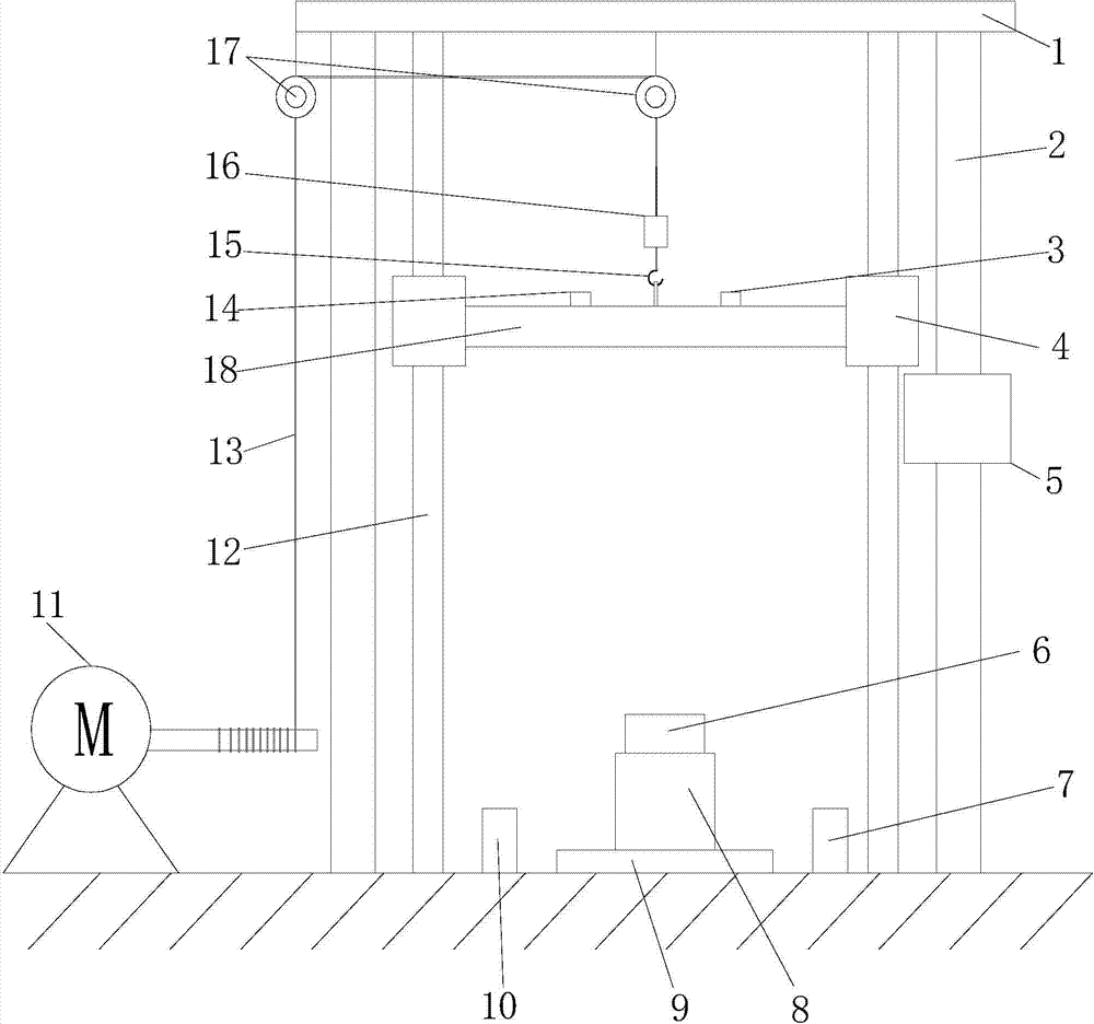
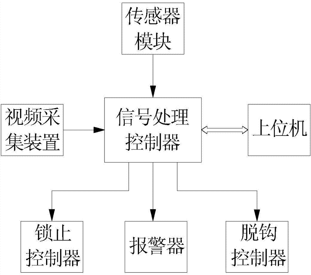
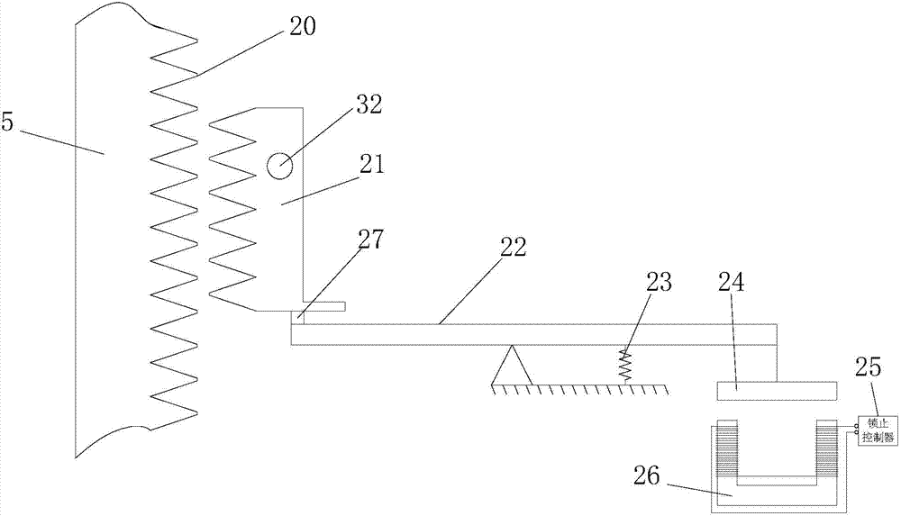
[0024] figure 1 It is a structural schematic diagram of the present invention, figure 2 It is the schematic circuit diagram of the present invention, image 3 It is the principle diagram of the failure protection device of the present invention, Figure 4 Be that the ratchet of fail-safe device of the present invention is in image 3 in the left view, Figure 5 It is a schematic diagram of the suspension assembly of the present invention, Figure 6 It is a structural schematic diagram of the vibration test of the present invention. As shown in the figure, a vertical drop impact test system provided by the present invention includes an adjustable mass load 18 for impacting the device under test 8, and is used to control the adjustable mass load. The suspension assembly at the height where the load 18 falls, the monitoring subsystem for monitoring the impact process, the support frame and the failure protection device, the monitoring subsystem controls the action of the sus...


PUM


Abstract

The invention provides a vertical dropping impact test system which comprises a weight-adjustable load, a suspension assembly, a monitoring subsystem, a support frame and a failure protective device. The weight-adjustable load is used for impacting a tested device, the suspension assembly is used for controlling the dropping height of the weight-adjustable load, and the monitoring subsystem is used for monitoring impact procedures; the weight-adjustable load is arranged on the support frame and can move up and down along the support frame, the tested device is arranged right below the weight-adjustable load, the suspension assembly is arranged on the support frame and can adjust the dropping height of the weight-adjustable load, the failure protective device is arranged on the support frame, can move up and down along the support frame and can be locked with the support frame so that the weight-adjustable load can stop dropping, and the suspension assembly and the failure protective device can act under the control of the monitoring subsystem. The vertical dropping impact test system has the advantages that integral procedures of impact or vibration tests and test parameters can be completely recorded, test results are accurate, and the vertical dropping impact test system is high in reliability.

Description

technical field [0001] The invention relates to a test system, in particular to a vertical drop impact test system. Background technique [0002] Before passive actuators, semi-active actuators, and active actuators are applied to actual shock or vibration control systems, the research and development process must go through the testing and evaluation of the mechanical properties of the devices themselves and the evaluation of the entire system based on the above devices. The testing and evaluation of the shock / vibration control effect. Among them, the passive actuator refers to the actuator applied to the passive system. The passive actuator cannot change its properties in real time according to the change of the system application environment. Typical passive actuators include rubber, Felts, springs, shock absorbers, etc.; active actuators are actuators that change their properties and provide effective driving actions when energy is applied externally, such as magnetostri...

Claims


Application Information

Patent Timeline
Patent Type & Authority Applications(China)
IPC IPC(8): G01M7/08G01M7/02
Inventor 白先旭钱立军祝安定
Owner HEFEI UNIV OF TECH
Why Eureka
Try Eureka