High-speed dynamic compression testing device

A dynamic compression, high-speed technology, applied in the direction of applying stable tension/pressure to test the strength of materials, etc., can solve the problems that the sample cannot be loaded at a constant speed and the strain rate changes greatly, and achieve low manufacturing cost and simple device structure , to avoid the effect of damaging the equipment

Active Publication Date: 2014-12-24
AUTOMOBILE RES INST OF TSINGHUA UNIV IN SUZHOU XIANGCHENG
View PDF6 Cites 7 Cited by
  • Summary
  • Abstract
  • Description
  • Claims
  • Application Information

AI Technical Summary

Problems solved by technology

Although the drop weight test bench can realize dynamic compression, due to the energy loss during the impact process, it is impossible to load the sample at a constant speed, and the strain rate changes greatly during the test

Method used


Image

  • High-speed dynamic compression testing device
  • High-speed dynamic compression testing device
  • High-speed dynamic compression testing device

Examples


Embodiment Construction

[0027] The present invention will be further described below in conjunction with the accompanying drawings:

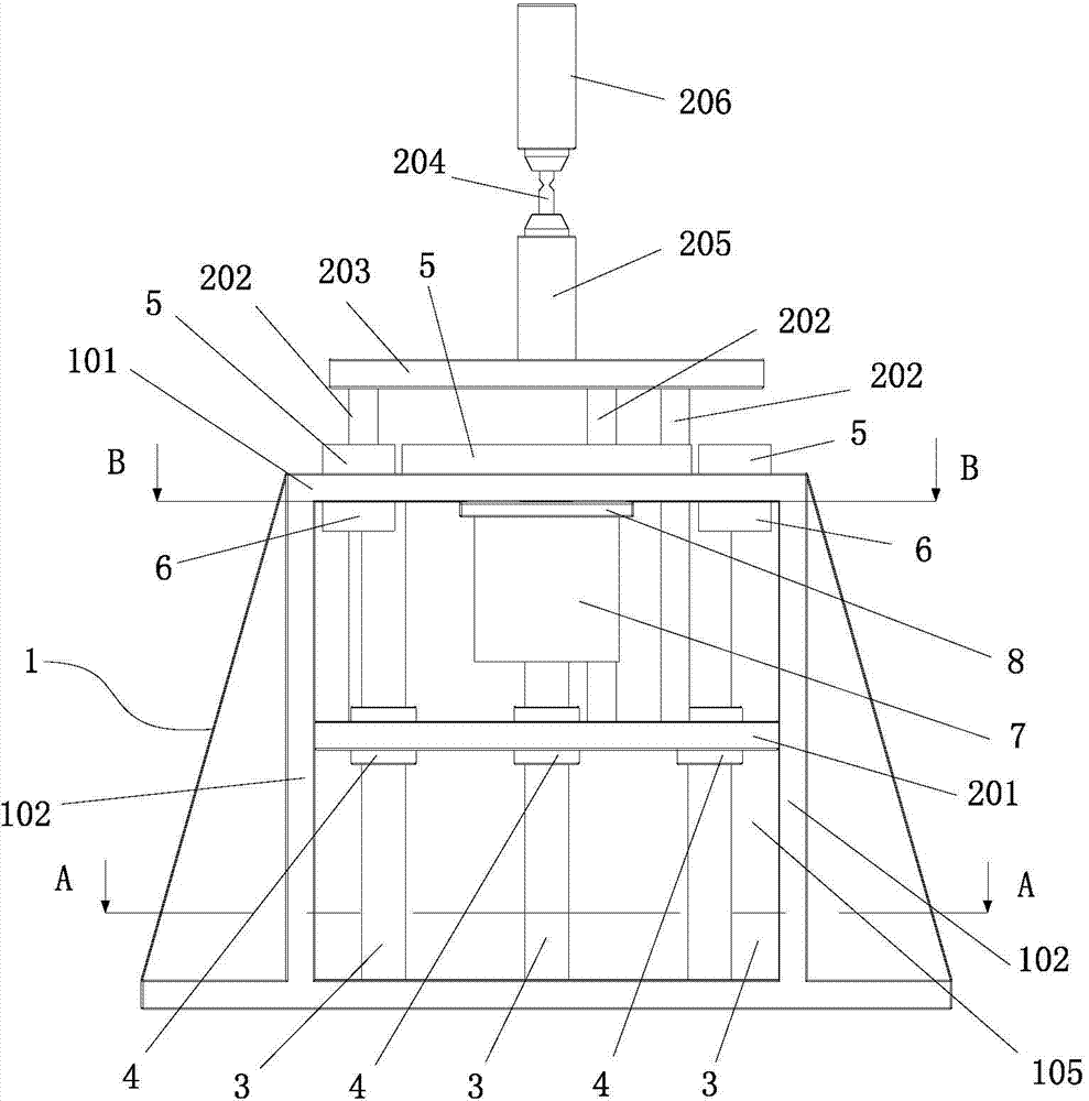
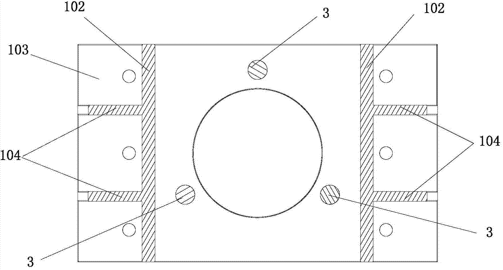
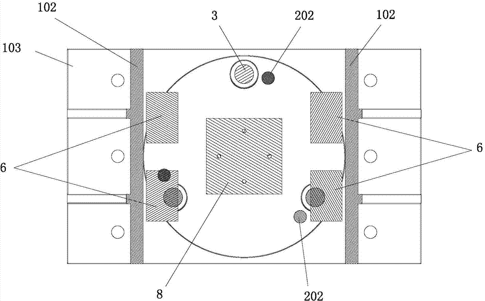
[0028] as attached Figures 1~7 As shown, a high-speed dynamic compression test device is used for a high-speed tensile testing machine. The device includes a base 1 for installing a test specimen 7 and a loading mechanism 2 for compressing the specimen 7. The loading mechanism 2. It includes a pressure plate 201 for compressing the test piece 7 and a connecting rod 202 fixedly connected to the pressure plate 201 at one end. The base 1 has a cavity 105 for accommodating the test piece 7 and the pressure plate 201 and a mounting plate for installing the test piece 7 101, one end of the connecting rod 202 is located in the cavity 105, and the other end extends through the mounting plate 101 to the outside of the cavity 105, and the connecting rod 202 is slidably arranged with the mounting plate 101, and the loading mechanism 2 also includes a surface with The other end ...


PUM


Abstract

The invention relates to a high-speed dynamic compression testing device. The high-speed dynamic compression testing device comprises a base for mounting a test piece and a loading mechanism for performing compression loading on the test piece; the loading mechanism comprises a pressing plate for compressing the test piece and a connecting rod of which one end portion is fixedly connected with the pressing plate; the base is provided with a cavity for holding the test piece and the pressing plate, and a mounting plate for mounting the test piece; one end portion of the connecting rod is located in the cavity, while the other end portion of the connecting rod penetrates through the mounting plate and extends out of the cavity, and the connecting rod is arranged in such a manner of sliding relatively to the mounting plate; the loading mechanism further comprises a loading plate of which one surface is fixedly connected with the other end portion of the connecting rod, and an unloading rod which is fixedly connected with the other side surface of the loading plate. The high-speed dynamic compression testing device can be directly applied to a high-speed tensile testing machine, is capable of realizing high-speed dynamic compression at low, medium and high different strain rates, and is safe and reliable.

Description

technical field [0001] The invention belongs to the field of dynamic testing and characterization of mechanical properties of materials and is used in industries such as automobiles and aviation, in particular to a device for high-speed dynamic compression testing. Background technique [0002] The mechanical behavior of lightweight materials under vehicle crash load depends on the stress state, and the fracture mechanical properties of metal materials such as high-strength steel under dynamic loads are related to the local tensile, compressive, and shear deformations of the material. The yield and fracture mechanical behaviors of non-metallic materials such as polymers under dynamic loading have a more significant correlation with the stress state. Therefore, it is necessary to obtain the dynamic mechanical behavior (such as dynamic compression) of materials under different stress states by experimental means to fully characterize the mechanical constitutive relationship of...

Claims


Application Information

Patent Timeline
Patent Type & Authority Applications(China)
IPC IPC(8): G01N3/08
Inventor 赖兴华黄毅尹斌曹家健王磊夏勇周青
Owner AUTOMOBILE RES INST OF TSINGHUA UNIV IN SUZHOU XIANGCHENG
Why Eureka
Try Eureka