Optical signal transmitting device

A transmission device and optical signal technology, applied in the direction of bundled optical fiber, etc., can solve the problems of loose optical fiber and affecting product performance, and achieve the effect of not easy to loose and simple structure

Active Publication Date: 2014-12-24
CHINA AVIATION OPTICAL-ELECTRICAL TECH CO LTD
View PDF7 Cites 10 Cited by
  • Summary
  • Abstract
  • Description
  • Claims
  • Application Information

AI Technical Summary

Problems solved by technology

The problem with this existing optical signal transmission device is that the upper and lower substrates need to be fixed by a fixed structure, and the setting of the fixed structure will increase the structural complexity of the optical signal transmission device. In addition, the fixed structure cannot necessarily ensure the stability of the upper and

Method used


Image

  • Optical signal transmitting device
  • Optical signal transmitting device
  • Optical signal transmitting device

Examples


Example Embodiment

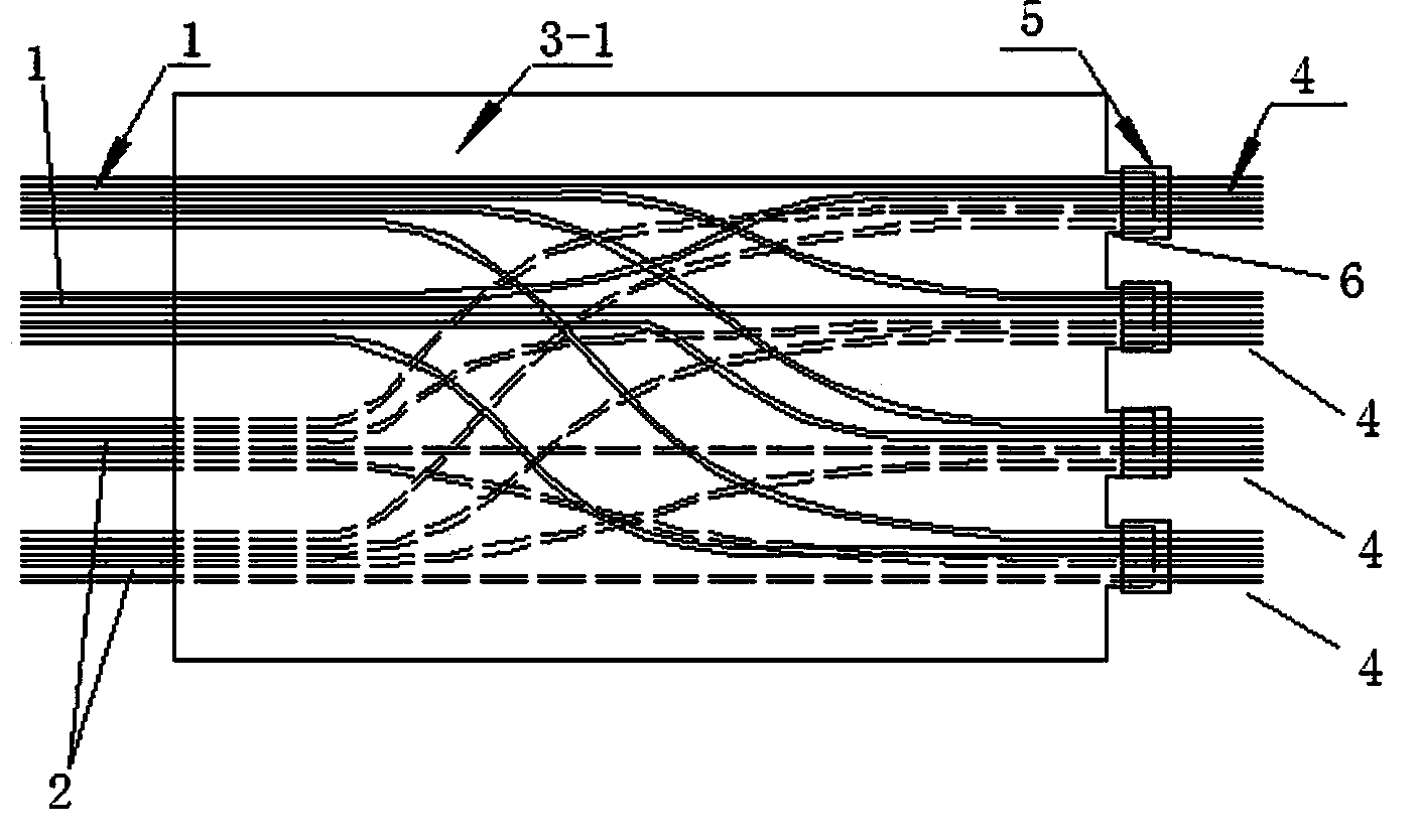
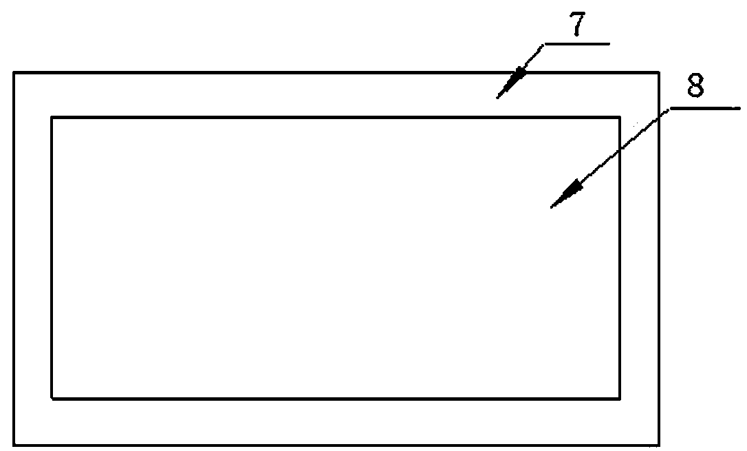
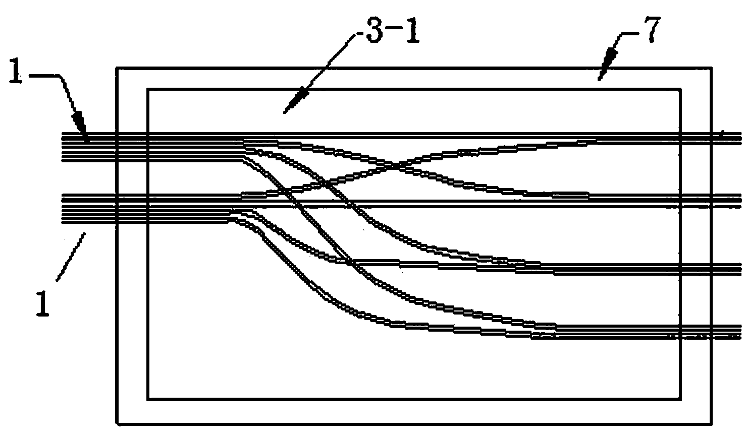
[0015] An example of an optical signal transmission device Figure 1~5 Shown: It includes a substrate with a thickness extending in the up and down direction. The substrate is a transparent adhesive film structure formed by curing glue. The adhesive film structure is pressure-sensitive. The substrate composed of the adhesive film structure itself is flexible and bendable. The pressure-sensitive layer will be formed on the upper and lower surfaces. The pressure-sensitive layer on the upper surface is provided with two incoming fiber ribbons 1 and the pressure-sensitive layer on the lower surface is provided with two incoming fiber optic tapes 2, each The optical fiber ribbons each include four optical fibers. The fiber inlet ends of the two incoming fiber ribbons 1 are spaced left and right, and the fiber incoming ends of the two incoming fiber ribbons 2 are spaced left and right. After the corresponding optical fibers are cross-recombined, four outgoing optical fiber ribbons 4 ...


PUM


Abstract

The invention relates to an optical signal transmitting device which comprises a base body with the thickness extending in the vertical direction. An upper packaging layer and a lower packaging layer are arranged on the upper surface and the lower surface of the base body respectively. At least one fiber inlet upper optical fiber band is fixedly arranged in the upper packaging layer. At least one fiber inlet lower optical fiber band is fixedly arranged in the lower packaging layer. Corresponding optical fibers in the fiber inlet upper optical fiber bands and the fiber inlet lower optical fiber bands are intersected and recombined for forming at least two fiber outlet optical fiber bands. The optical signal transmitting device is simple in structure, and the optical fibers of the fiber outlet optical fiber bands are not prone to loosening.

Description

technical field [0001] The present invention relates to optical signal transmission devices using crossed optical fiber ribbons. Background technique [0002] With the continuous development of information technology, optical fibers are used in more and more communication systems. In order to achieve high-density transmission of optical signals, the application of optical fiber ribbons containing multiple optical fibers is born. The traditional optical fiber ribbons are in the form of flat ribbons. , which consists of 8, 12 or 24 bare optical fibers side by side. When in use, a special type of connector is made at the input end of the optical fiber and the output end of the optical fiber to transmit optical signals. When this form of optical fiber transmits signals, there is a one-to-one correspondence between the signals at one end and the other end, and the signal cannot be transmitted from one optical fiber ribbon to another optical fiber ribbon. With the increasing amou...

Claims


Application Information

Patent Timeline
IPC IPC(8): G02B6/08
Inventor 彭川黄澄张晓光
Owner CHINA AVIATION OPTICAL-ELECTRICAL TECH CO LTD
Why Eureka
Try Eureka