Polarized light radiating device for optical orientation and polarized light radiating method for optical orientation

An irradiating device, a technology of polarized light, applied in polarizing elements, optics, optical elements, etc., can solve problems such as large degrees of freedom, and achieve the effects of improved productivity, simplified structure and operation, and uniform exposure.

Active Publication Date: 2014-12-24
USHIO DENKI KK
View PDF7 Cites 8 Cited by
  • Summary
  • Abstract
  • Description
  • Claims
  • Application Information

AI Technical Summary

Problems solved by technology

In the case where such a plate-shaped member is a workpiece, various chan

Method used


Image

  • Polarized light radiating device for optical orientation and polarized light radiating method for optical orientation
  • Polarized light radiating device for optical orientation and polarized light radiating method for optical orientation
  • Polarized light radiating device for optical orientation and polarized light radiating method for optical orientation

Examples


Embodiment

[0139] Next, the result of the experiment which confirmed that the exposure amount became uniform by introducing the conveyance of the board|substrate S in the 2nd direction as mentioned above is demonstrated as an Example. Figure 13It is a figure which shows the result of the experiment which confirmed that the cumulative exposure amount becomes uniform by introducing the conveyance of the board|substrate S in a 2nd direction.

[0140] In this experiment, the width of the irradiated region R viewed in the second direction was 1500mm, the light source 3 was a high-pressure mercury lamp, and the average illuminance in the irradiated region R was about 130mW / cm 2 .

[0141] The width t of each polarizing element 41 is 150 mm, so the distance between the boundary lines is 150 mm. exist Figure 13 In (1), the exposure amount distribution is shown when the substrate S is conveyed in the same path in the forward path and the return path without moving in the second direction, and...


PUM


Abstract

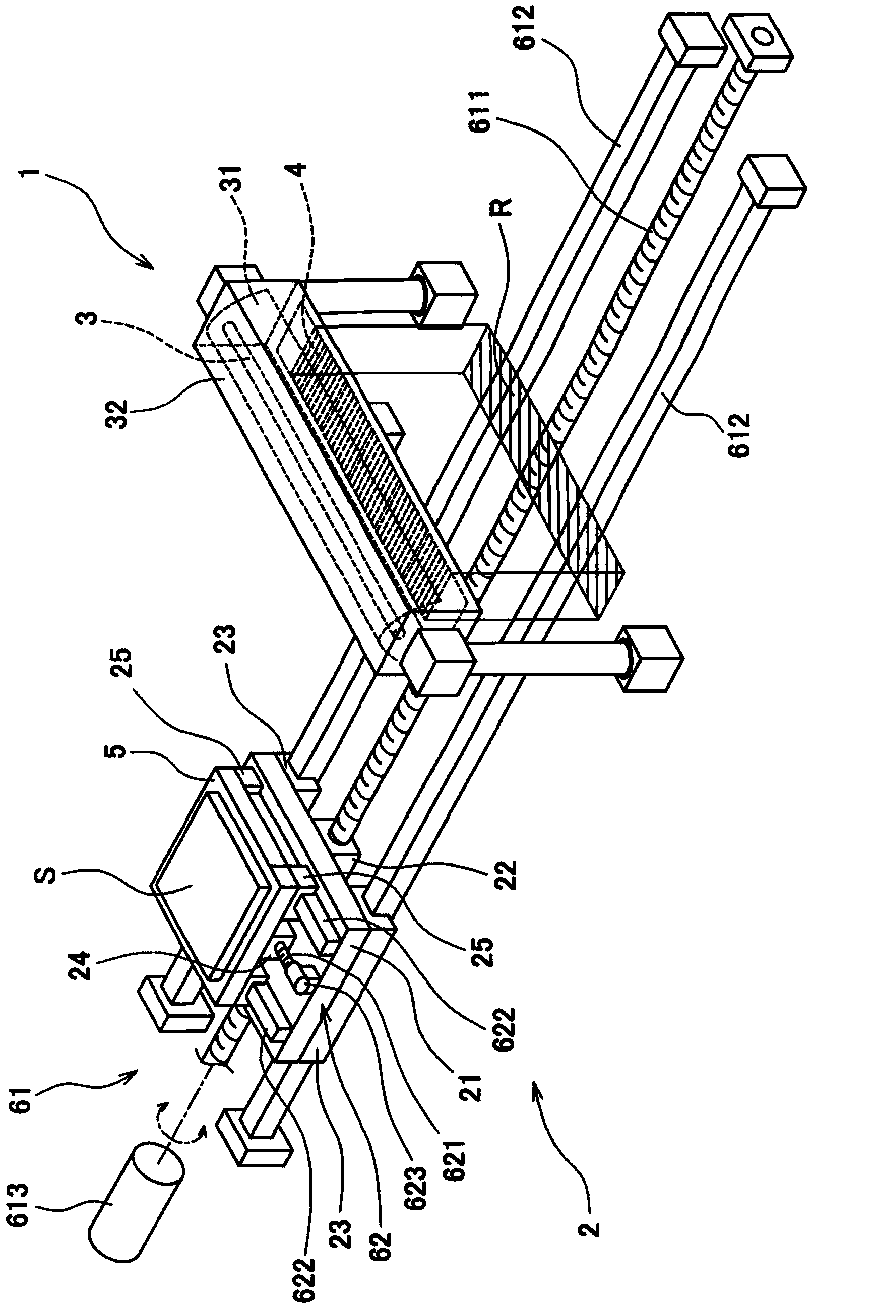
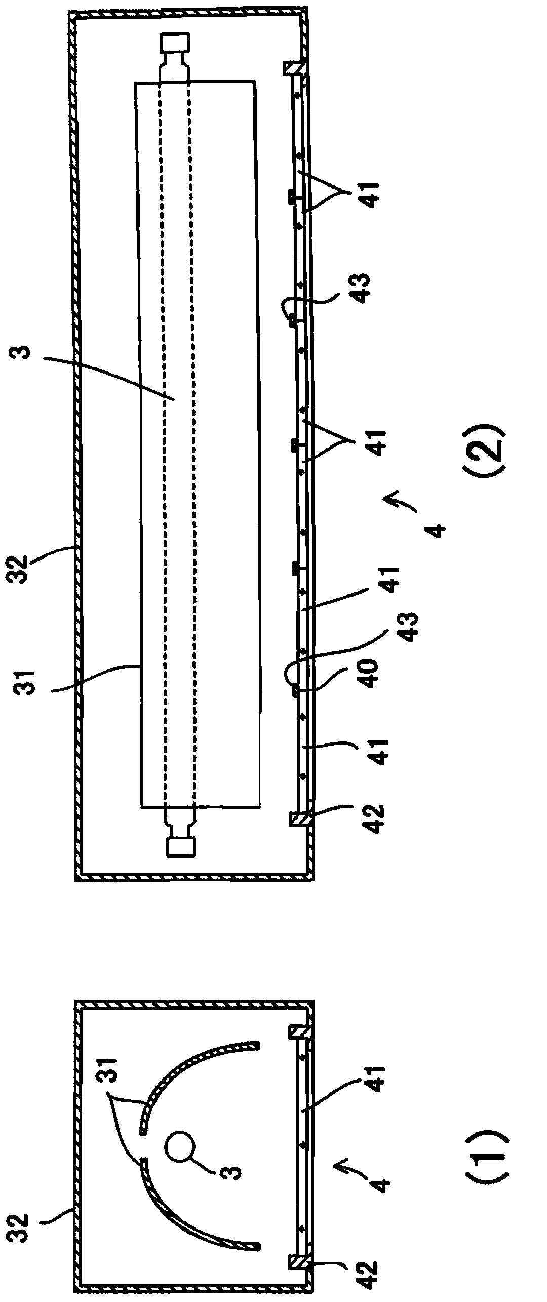
The invention provides a polarized light radiating device for optical orientation and a polarized light radiating method for optical orientation, wherein practical optical orientation technology which can improve uniformness of an exposed surface through elaborately designing a conveying system is adopted. Light from a light source (3) which forms an elongated light emitting part is radiated to a radiating area (R) through a polarizing element unit (4). A conveying system (2) conveys a substrate (S) in one direction and makes the substrate simultaneously pass through the radiating area (R) and reciprocate. The boundary (40) of each polarizing element (41) extends along a first direction. The conveying system (2) conveys the substrate (S) in a second direction after going-path conveying and before returning-path conveying. Because the polarized light radiating device is in a state that the position of the boundary (40) changes when observed from the substrate (S), uniform exposure amount is realized.

Description

technical field [0001] The present invention relates to a technique for irradiating polarized light when performing photo-alignment. Background technique [0002] In recent years, when obtaining the alignment film of the liquid crystal display element represented by a liquid crystal panel, and the alignment layer of a viewing angle compensation film, the technique called photo-alignment which performs alignment by light irradiation is used gradually. Hereinafter, films and layers aligned by light irradiation are collectively referred to as photo-alignment films. In addition, "orientation" or "orientation processing" means giving directionality to some property of an object. [0003] Photo-alignment is performed by irradiating polarized light to the film for photo-alignment films (henceforth film material). The film material is made of resin such as polyimide, and polarized light polarized in a desired direction (direction to be aligned) is irradiated to the film material. ...

Claims


Application Information

Patent Timeline
IPC IPC(8): G02B27/28G02B5/30G02F1/1337
CPCG02B5/3025G02F1/1303G02F1/133788
Inventor 筱田和敏
Owner USHIO DENKI KK
Why Eureka
Try Eureka