
Segmented device for rotor butt joint assembly and method for conducting rotor butt joint assembly with device

A segmented, rotor technology, applied in the manufacture of stator/rotor body, etc., can solve the problems of accurate centering and positioning, high cost, labor and time-consuming, etc., and achieve the effect of fast centering and positioning, and accurate centering and positioning.

Active Publication Date: 2014-12-24
DONGFANG TURBINE CO LTD
View PDF3 Cites 2 Cited by
  • Summary
  • Abstract
  • Description
  • Claims
  • Application Information

AI Technical Summary

Problems solved by technology

Although the separate manufacturing of the rotor segments at least overcomes the problems in the overall manufacturing mentioned above, however, it faces new technical difficulties in the construction of butt joint assembly, one of which is how to realize the butt joint assembly of small forgings in each segment The problem of mutual accurate alignment and positioning. For example, when the rotor is divided into the upper shaft head and the lower shaft head, butt assembly is carried out. Due to the lack of docking assembly equipment to ensure accurate alignment of the rotor, repeated measurements and adjustments are required during construction. To meet the alignment accuracy requirements of the rotor docking assembly, it is labor-intensive and time-consuming, the rotor docking assembly has low efficiency and high cost, and the alignment accuracy cannot be guaranteed
Obviously, not only the rotors of the above-mentioned water turbines and steam turbines will face at least the aforementioned problem of how to accurately align and position when they are docked and assembled, but also the rotors of other machinery and equipment will face the same problem when they are segmented and assembled

Method used


Image

  • Segmented device for rotor butt joint assembly and method for conducting rotor butt joint assembly with device
  • Segmented device for rotor butt joint assembly and method for conducting rotor butt joint assembly with device
  • Segmented device for rotor butt joint assembly and method for conducting rotor butt joint assembly with device

Examples


Embodiment Construction

[0039] In order to describe the technical features and functions of the present invention in detail and realize them according to the content of this specification, the following takes a segmented rotor of a steam turbine / combustion engine as an example to further describe the embodiment of the present invention.

[0040] Figure 7 to Figure 9 It only shows a segmented rotor of the steam turbine / gas engine involved in the present invention in a schematic manner. Since the technical solution of the present invention does not involve other components and shape structures of the segmented rotor, Figure 7 to Figure 9 The figure only briefly shows the general structure of the segmented rotor divided into two butt-joint segments, obviously the shape and structure of the actual rotor is more complicated. Figure 7 to Figure 9 The lower shaft head 400 and the upper shaft head 500 of the segmented rotor are shown. For the convenience of description, the lower shaft head 400 of the segm...


PUM


Abstract

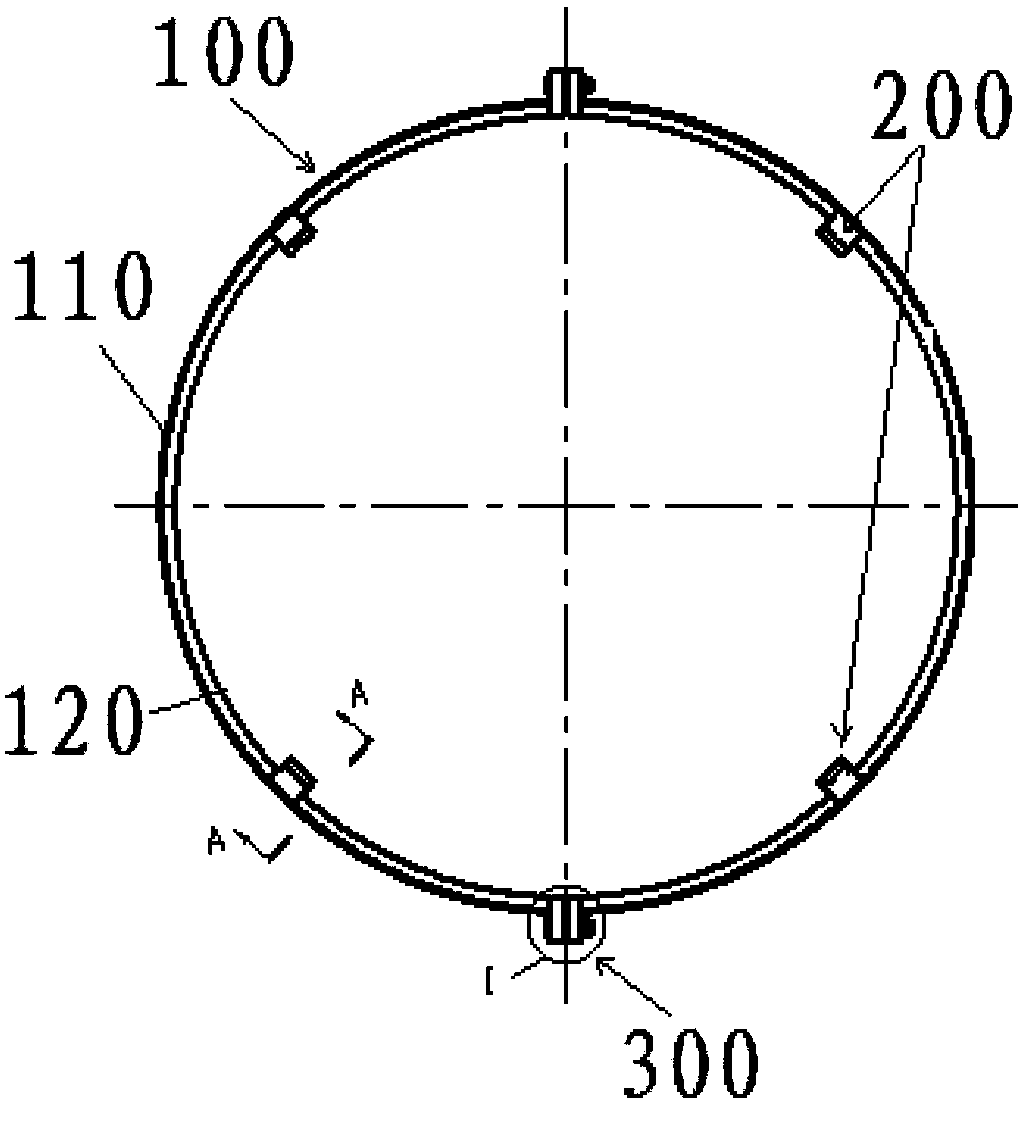
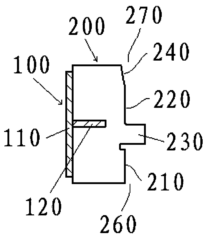
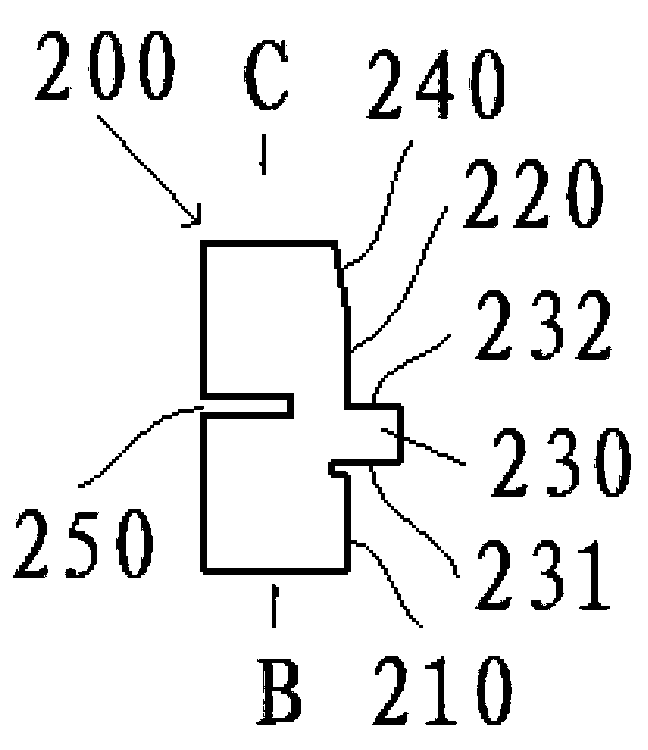
The invention discloses a segmented device for rotor butt joint assembly. The device comprises a shroud ring and a plurality of guiding and centering positioning parts peripherally arranged along the peripheral wall of an inner ring of the shroud ring at intervals. The face, facing the center of the inner ring of the shroud ring, of each guiding and centering positioning part is provided with a first groove matched with an arc face of the outer circle face of a welding notch of a first butt joint segment of a rotor, and a second groove matched with the arc face of the outer circle face of a welding notch of a second butt joint segment of the rotor, and the arc face of the first groove and the arc face of the second groove of the same guiding and centering part are concentric. The arc faces of the first grooves of the guiding and centering positioning parts are concentric or the arc faces of the second grooves of the guiding and centering positioning parts are concentric. The invention further discloses a method for conducting rotor butt joint assembly with the device. By means of the device and the method, the two butt joint segments of the rotor can be conveniently, rapidly and accurately centered and positioned, the butt joint assembly quality of the rotor is ensured, and the time for butt joint assembly of the rotor can be saved.

Description

technical field [0001] The invention relates to a rotor docking assembly equipment and method, in particular to a segmented rotor docking assembly device and a rotor docking assembly method using the same. Background technique [0002] In engineering, common machinery and equipment, such as aeroengines, various compressors, generators, electric motors, water turbines, steam turbines and gas turbines, etc., are equipped with rotating parts, namely rotors. The rotors of these machinery and equipment are generally manufactured as a whole. For the rotors of large steam turbines, water turbines and other equipment, the overall forging size is huge, which requires high production equipment and technology. Manufacturing is difficult and costly, and quality is also difficult to guarantee. In order to overcome the above problems, the method currently used is: first divide the rotor into two or more small forgings and manufacture them separately. These segmented small forgings are bu...

Claims


Application Information

Patent Timeline
IPC IPC(8): H02K15/02
Inventor 曹天兰张从平钟玉杨冬陈仲明郑亮亮徐虎
Owner DONGFANG TURBINE CO LTD
Features
  • Generate Ideas
  • Intellectual Property
  • Life Sciences
  • Materials
  • Tech Scout
  • Unparalleled Data Quality
  • Higher Quality Content
  • 60% Fewer Hallucinations
Learn More