Trans-impedance amplification circuit capable of realizing automatic gain control

A technology of automatic gain control and transimpedance amplification, applied in gain control, DC-coupled DC amplifier, amplification control, etc., can solve the problems of stability margin drop, signal processing ringing, insufficient loop stability margin, etc. Achieve the effect of loop gain reduction and large stability margin

Active Publication Date: 2014-12-24
XIAMEN UX HIGH SPEED IC
View PDF6 Cites 10 Cited by
  • Summary
  • Abstract
  • Description
  • Claims
  • Application Information

AI Technical Summary

Problems solved by technology

This structure has a disadvantage: when the automatic gain loop starts to work, the dominant pole of the loop moves to high frequency due to the reduction of transimpedance, and the stability margin decreases because the loop gain does not change, and the signal processing will be degraded. Ringing occurs, so large input dynamics cannot be met
[0007] These two shortcomings create two insurmountable problems
[0008] 1. When the automatic gain control loop is turned on and Vcon is small, the bandwidth of the transimpedance amplifier circuit may not be large enough to handle high-speed signals due to the sudden decrease of the loop gain
[0009] 2. When the automatic gain control loop is turned on and Vcon exceeds a certain value, since the loop gain cannot continue to decrease, the stability margin of the loop may be insufficient, and ringing will occur after signal processing

Method used


Image

  • Trans-impedance amplification circuit capable of realizing automatic gain control
  • Trans-impedance amplification circuit capable of realizing automatic gain control
  • Trans-impedance amplification circuit capable of realizing automatic gain control

Examples


Embodiment 1

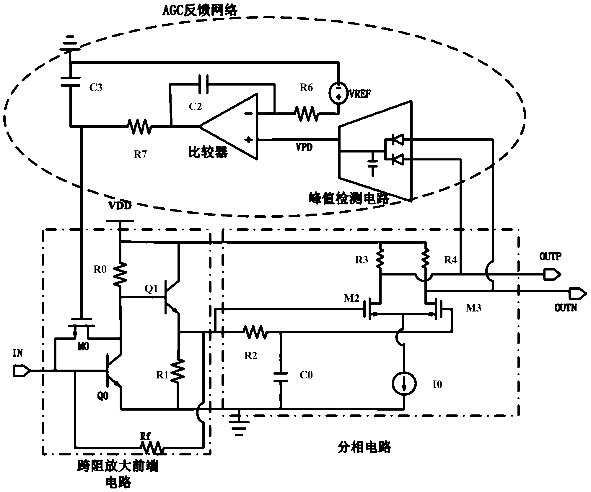
[0039] refer to image 3 , a transimpedance amplifier circuit capable of automatic gain control, comprising:

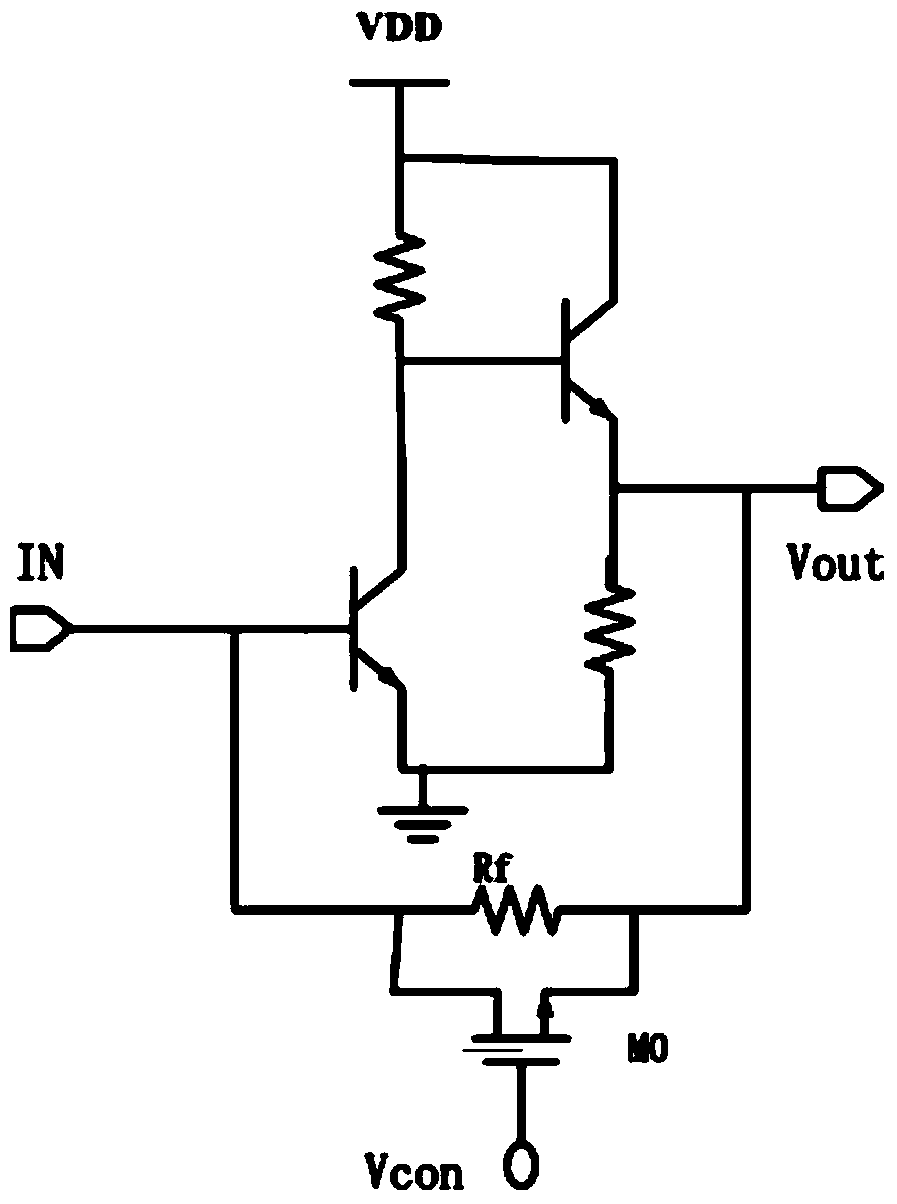
[0040] Transimpedance amplification front-end circuit, the transimpedance amplification front-end circuit converts the input current signal into a voltage signal, including the first switch tube Q0, the second switch tube Q1 and the first MOS tube M0, the first switch tube in this embodiment Q0 and the second switching tube Q1 are preferably triodes; the collector of the first switching tube Q0 is connected to the base of the second switching tube Q1; the base of the first switching tube Q0 is connected to the second switching tube through the transimpedance Rf The emitter of the transistor Q1 is connected; the source of the first MOS transistor M0 is connected to the base of the first switching transistor Q0, and the drain of the first MOS transistor M0 is connected to the collector of the first switching transistor Q0 Electrode connection; the first MOS transistor ...

Embodiment 2

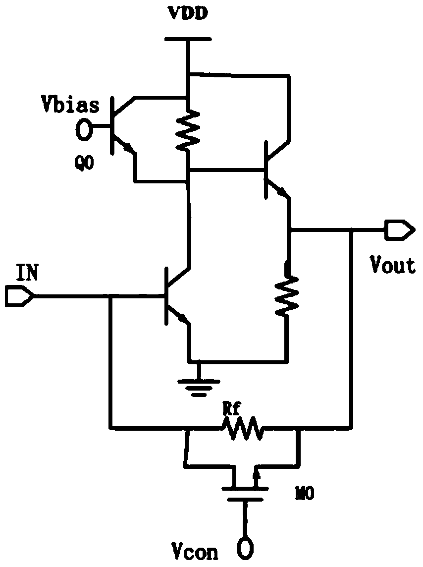
[0061] refer to Figure 5 , the difference from Example 1 is:

[0062] The transimpedance amplification front-end circuit further includes a third switching tube Q2, the emitter of the third switching tube Q2 is connected to the collector of the first switching tube Q0; the collector of the third switching tube Q2 is connected to the first switching tube Q2 The bases of the two switch tubes Q1 are connected. The third switching transistor Q2 is a cascode stage or a cascode stage, which can increase circuit bandwidth. The remaining parts are the same as those in Embodiment 1, so they will not be repeated here.

[0063] In this embodiment, the first switching tube Q0 , the second switching tube Q1 and the third switching tube Q2 are triodes, and can also be replaced with MOS tubes as required.

Embodiment 3

[0065] refer to Figure 6 , the difference from Example 2 is:

[0066] The second MOS transistor M1 is connected in parallel on both sides of the transimpedance Rf, the second MOS transistor M1 controls the transimpedance Rf, and the first MOS transistor M0 controls the loop gain, which further ensures the stability of the circuit. The rest of this embodiment is the same as the second embodiment, so it will not be repeated.


PUM


Abstract

The invention provides a trans-impedance amplification circuit capable of realizing automatic gain control. The trans-impedance amplification circuit comprises a trans-impedance amplification front end circuit, a phase splitting circuit and an AGC feedback network, wherein the trans-impedance amplification front end circuit converts input current signals into voltage signals, and comprises a first switch tube, a second switch tube and a first MOS tube, a collector electrode of the first switch tube is connected with a base electrode of the second switch tube, a base electrode of the first switch tube is connected with an emitting electrode of the second switch tube through trans-impedance, a source electrode of the first MOS tube is connected with the base electrode of the first switch tube, a drain electrode of the first MOS tube (M0) is connected with the collector electrode of the first switch tube, the AGC feedback network comprises a peak value detection circuit and a comparison circuit, the peak value detection circuit detects differential voltage signals output by the phase splitting circuit and outputs direct current voltage, the comparison circuit detects the direct current voltage output by the peak value detection circuit and compares the direct current voltage with a reference level, and the output end of the comparison circuit is connected with a grid electrode of the first MOS tube.

Description

technical field [0001] The invention relates to a transimpedance amplifying circuit, in particular to a transimpedance amplifying circuit capable of realizing automatic gain control. Background technique [0002] A transimpedance amplifier is an electronic circuit that converts a current signal into a voltage signal and amplifies it. It is often used as the front-end circuit of an optical communication receiving chip. The transimpedance amplifier circuit needs to have a large enough input dynamic range to meet the application. In order to ensure that the transimpedance amplifier circuit can handle large signals, it is necessary to introduce an automatic gain control mechanism in the transimpedance amplifier circuit, that is, when the input signal is greater than a certain value, the circuit The automatic gain loop starts to work, reducing the gain of the transimpedance amplifier circuit, so as to achieve the function of processing large signal input. [0003] There are main...

Claims


Application Information

Patent Timeline
Patent Type & Authority Applications(China)
IPC IPC(8): H03F3/45H03G3/20
Inventor 陈伟
Owner XIAMEN UX HIGH SPEED IC
Why Eureka
Try Eureka