
Sub-1G radio frequency front-end circuit design based on RF energy detection and parameter adjustment method based on RF energy detection

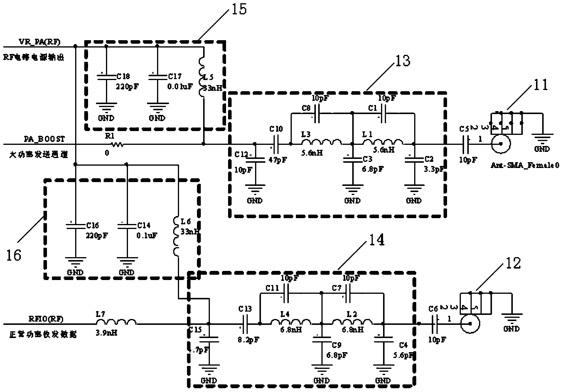
A radio frequency front-end and circuit design technology, applied in the field of radio frequency, can solve problems such as large power loss of transmission lines, complex structure of radio frequency front-end circuits, inability to detect and adjust component parameter values ​​of circuits, etc., and achieve high stability and reliability

Active Publication Date: 2014-12-24
南通森翔检测技术有限公司
View PDF4 Cites 8 Cited by
  • Summary
  • Abstract
  • Description
  • Claims
  • Application Information

AI Technical Summary

Problems solved by technology

[0003] The existing RF front-end circuits generally have complex structures, low system stability and reliability, large power loss on the transmission line, and the parameter values ​​of the components in the circuit are calculated theoretically, so the actual effect is far from ideal. There is no technical solution for adjusting the component parameter values ​​of the RF front-end circuit
Therefore, the existing RF front-end circuit design structure is unreasonable, and the component parameter values ​​​​of the circuit cannot be adjusted based on RF energy detection, so that the transmission of the maximum transmission power cannot be achieved

Method used


Image

  • Sub-1G radio frequency front-end circuit design based on RF energy detection and parameter adjustment method based on RF energy detection
  • Sub-1G radio frequency front-end circuit design based on RF energy detection and parameter adjustment method based on RF energy detection
  • Sub-1G radio frequency front-end circuit design based on RF energy detection and parameter adjustment method based on RF energy detection

Examples


Embodiment Construction

[0046] The present invention will be described more fully hereinafter with reference to the accompanying drawings, in which exemplary embodiments of the invention are illustrated.

[0047] An antenna is connected to the RF front-end circuit. Antenna is an important electronic component for wireless devices to send and receive electromagnetic wave signals. Whether it is radio communication, broadcasting, television, radar, navigation, electronic countermeasures, remote sensing and other communication engineering systems, all those that use electromagnetic waves to transmit information must rely on antennas to work. Therefore, the radio frequency antenna is also very important for wireless node communication. The quality of the antenna design will directly affect the quality of wireless signal transmission and reception, and affect the transmission and reception distance of wireless signals.

[0048] Common antennas currently on the market mainly include PCB antennas, Chip ante...


PUM


Abstract

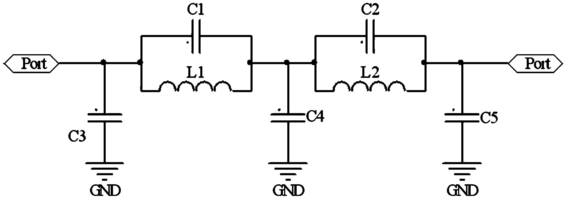
The invention discloses a sub-1G radio frequency front-end circuit design based on RF energy detection and a parameter adjustment method based on RF energy detection. The procedure for adjusting parameter values of components in a second-order elliptic function low-pass filter on the basis of RF energy detection specifically comprises the following steps that a channel energy value is obtained; energy loss of a wireless signal on a transmission line and the communication distance between nodes are calculated; according to the calculated energy loss on the transmission line and the communication distance between the nodes, the parameter values of the components of the second-order elliptic function filter are adjusted. The stability and the reliability of the designed Sub-1G radio frequency front-end circuit are high, the parameter values of the components in the second-order elliptic function low-pass filter can be adjusted on the basis of RF energy detection, the purpose that the transmission line and the impedance of the load are matched with the impedance of a radio frequency source is achieved by replacing the actual electronic component values of the radio frequency circuit, and transmission at the maximum transmission power is achieved.

Description

technical field [0001] The invention relates to the field of radio frequency technology, in particular to a Sub-1G radio frequency front-end circuit design and parameter adjustment method based on RF energy detection. Background technique [0002] The Sub-1G frequency band is an application-free transmission and reception frequency in our country. It can be used directly and has strong penetration. It is suitable for applications with many obstacles and wireless transmission. Sub-1G can be subdivided into four series of 433MHz, 470MHz, 868MHz, and 915MHz according to the wireless transmission frequency band. Compared with the 2.4G frequency band, the Sub-1G frequency band has a better effect in terms of coverage and capacity, and is currently widely used in the fields of mobile communications and wireless networks. [0003] The existing RF front-end circuits generally have complex structures, low system stability and reliability, large power loss on the transmission line, a...

Claims


Application Information

Patent Timeline
Patent Type & Authority Applications(China)
IPC IPC(8): H04B1/40H03H17/00
Inventor 王宜怀胡宗棠刘辉
Owner 南通森翔检测技术有限公司
Learn More