Circuit board control cabinet with replaceable pivot drive area

A technology of circuit board, driving area, applied in the field of maintenance of circuit board control cabinet

Inactive Publication Date: 2014-12-24
STATE GRID SHANDONG ELECTRIC POWER +1
View PDF3 Cites 4 Cited by
  • Summary
  • Abstract
  • Description
  • Claims
  • Application Information

AI Technical Summary

Problems solved by technology

[0005] The purpose of the present invention is to provide an electrical cabinet, which can use automatic control to facilitate ma

Method used


Image

  • Circuit board control cabinet with replaceable pivot drive area
  • Circuit board control cabinet with replaceable pivot drive area
  • Circuit board control cabinet with replaceable pivot drive area

Examples


Embodiment Construction

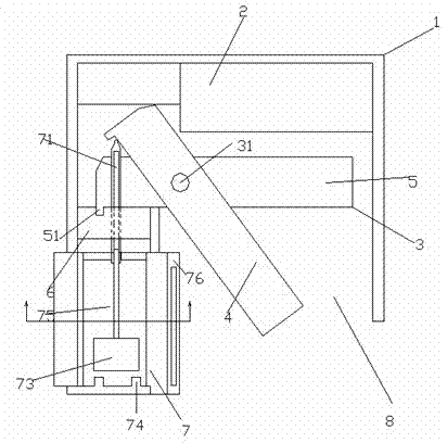
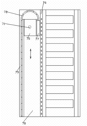
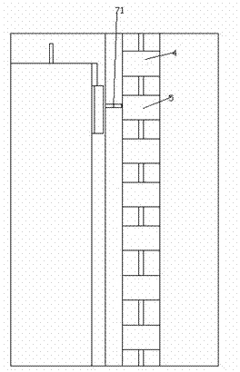
[0017] Combine below Figure 1-5 The present invention will be described in detail.

[0018] A circuit board control cabinet with a replaceable pivot drive area 41, comprising a cabinet shell 1, a ventilation system 2, a circuit board placement assembly 3, a fixing frame 6 and a lifting circuit board opening part 7, wherein the cabinet shell 1 is used for for accommodating the ventilation system 2, the circuit board mounting assembly 3, the fixing frame 6 and the lifting circuit board opening part 7 and having a doorway area 8, the doorway area 8 is used for the user to operate and maintain the circuit board control cabinet, The ventilation system 2 is used to input cooling air into the cabinet housing 1, and the circuit board mounting assembly 3 is provided with a column shaft 31 on which a plurality of circuit boards 4 are pivotably mounted from above and below. , 5, each of the circuit boards can be pivoted relative to the column shaft 31 independently of each other; the f...


PUM


Abstract

The invention discloses a circuit board control cabinet with a replaceable pivot drive area (41). The circuit board control cabinet comprises a cabinet shell (1), a ventilating system (2), a circuit board placement component (3), a fixed mount (6) and a lifting type circuit board opening component (7), wherein the cabinet shell (1) is used for accommodating the ventilating system (2), the circuit board placement component (3), the fixed mount (6) and the lifting type circuit board opening component (7), and provided with a gate area (8) where a user can operate and maintain the circuit board control cabinet; the ventilating system (2) is sued for inputting cooling air into the cabinet shell; the circuit board placement component (3) is provided with a stand column shaft (31) on which a plurality of circuit boards (4, 5) are pivotally installed from the top down, and the circuit boards can pivot relating to the stand column shaft (31) independently from one another.

Description

technical field [0001] The invention relates to a circuit board control cabinet of automation equipment, in particular to the maintenance of the circuit board control cabinet. Background technique [0002] Some large-scale automation equipment now requires a large number of circuit boards to control the actions of its various components due to its complex motion control. [0003] In order to make the maintenance of the control circuit boards of various components easier, and to provide a good operating environment for these circuit boards, all circuit boards of these control components are generally installed in an electrical cabinet uniformly. [0004] However, due to the huge volume of the circuit board and the consideration of the protection of the industrial environment, the circuit board often has a heavier shell weight and internal weight, and the insertion force of the circuit interface is often required to be higher and more stable, which reduces the maintenance of t...

Claims


Application Information

Patent Timeline
IPC IPC(8): H05K5/00H05K7/12H05K7/14H05K7/18
Inventor 李良芳
Owner STATE GRID SHANDONG ELECTRIC POWER
Why Eureka
Try Eureka