
Drum type washing machine

A drum-type washing machine and drum technology, which is applied to other washing machines, control devices of washing machines, washing devices, etc., can solve problems such as inability to operate, movement of washing machines, and increased vibration.

Active Publication Date: 2014-12-24
PANASONIC INTELLECTUAL PROPERTY MANAGEMENT CO LTD
View PDF8 Cites 18 Cited by
  • Summary
  • Abstract
  • Description
  • Claims
  • Application Information

AI Technical Summary

Problems solved by technology

The following problems arise: the washing machine itself moves due to the vibration, and the operation cannot be performed above a certain rotation speed due to the strong noise.
[0008] However, in the conventional structure, when the rotational speed of the drum 101 is lower than the resonance rotational speed, the unbalance between the rolling elements 103 and the laundry exists in the same phase position.
Therefore, there is a problem that the rolling element 103 acts as an imbalance with the laundry, so that the vibration may increase when passing the resonance rotation speed.
[0009] In addition, when detecting the eccentric amount and eccentric position of the laundry in the drum 101, the rolling element 103 also rotates simultaneously with the drum 101, so it is difficult to detect the eccentric state of the laundry with high accuracy.
In addition, there is a problem that the rolling element 103 used to eliminate the imbalance becomes the cause of the imbalance due to an eccentric state such as a small amount of eccentricity of the laundry.

Method used


Image

  • Drum type washing machine
  • Drum type washing machine
  • Drum type washing machine

Examples


no. 1 approach

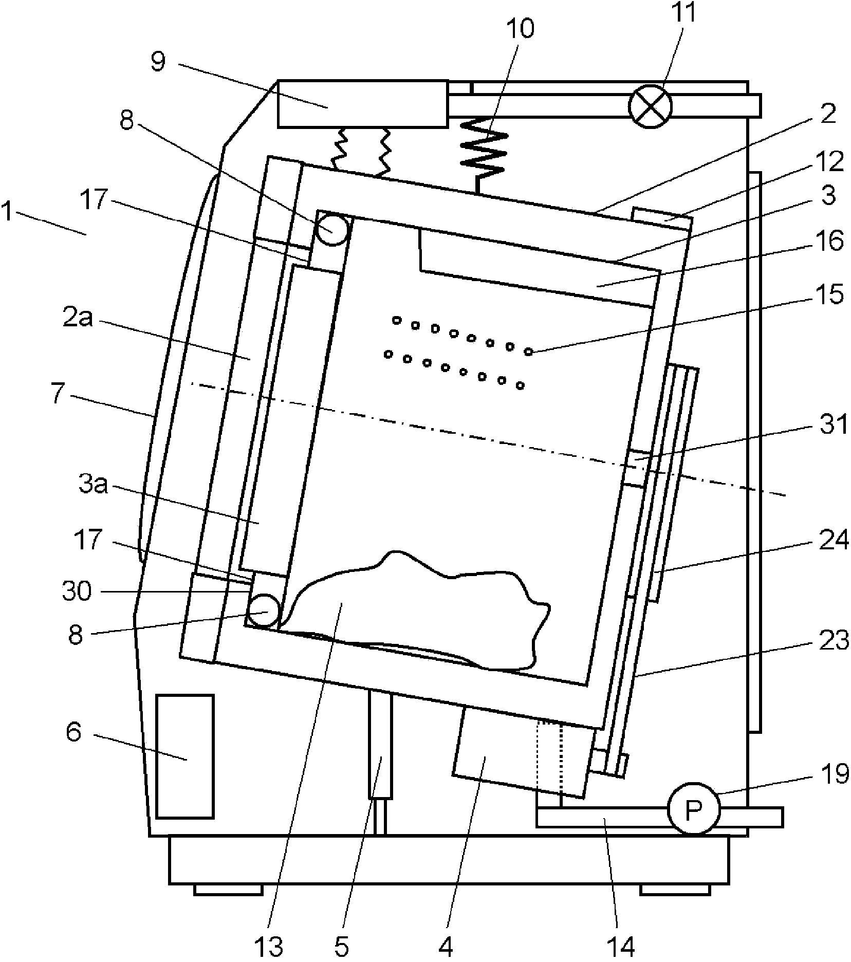
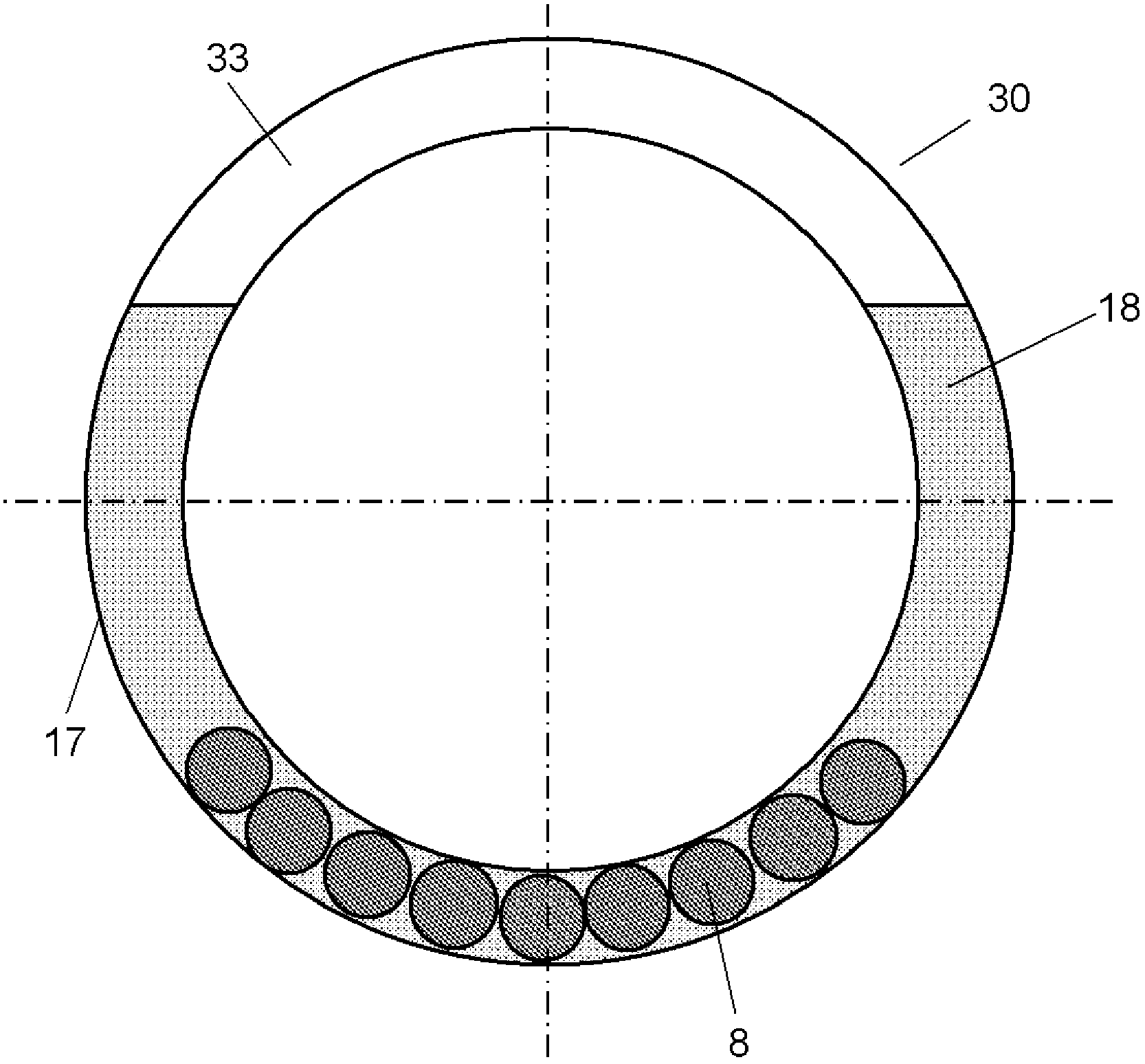
[0030] figure 1 It is a block diagram of the front-loading-type washing machine of Embodiment 1 of this invention. figure 2 It is a schematic diagram of the ball balancer which concerns on 1st Embodiment of this invention.

[0031] A bottomed cylindrical water tank 2 is accommodated inside the drum type washing machine 1 . A bottomed cylindrical drum 3 is accommodated inside the water tank 2 . On the front side of the front-loading-type washing machine 1, an opening 3a communicating with the inside of the drum 3 through the opening 2a of the water tank 2 is formed. The drum 3 is arranged so that the rotating shaft 31 that rotatably supports the drum 3 is inclined downward from the front side toward the back side. The opening part 2a is made into the front side, and the water tank 2 is arrange|positioned obliquely along the drum 3. As shown in FIG. By tilting the rotating shaft 31, the opening on the front side of the water tank 2 can be arranged on the upper side, and th...

no. 2 approach

[0056] Another mode of the starting process of the rotational speed of the drum will be described.

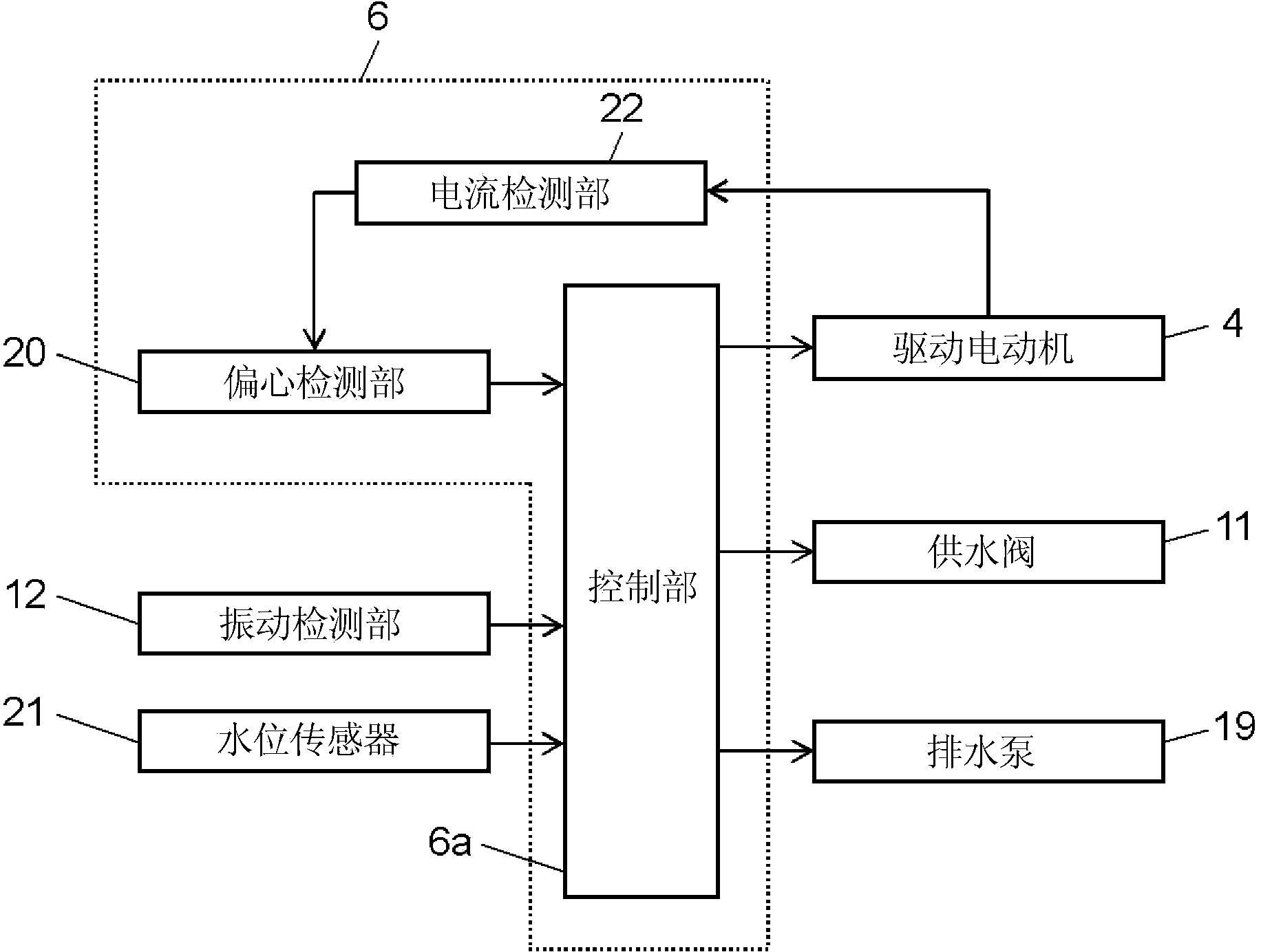
[0057] The control unit 6a of the front-loading-type washing machine according to the second embodiment of the present invention performs the following control. That is, the control unit 6a determines that the drum is being accelerated from the eccentric amount and eccentric position of the drum 3 before acceleration and the unbalance of the drum 3 during acceleration and the eccentric amount when the rolling elements 8 rotate together, based on the signal obtained by the eccentricity detecting unit 20 . Each rolling body is the position of the rolling body 8. Then, the drive motor is controlled so that the unbalance of the rolling element 8 and the laundry is at a position facing each other. Other structures refer to the first embodiment of the present invention. Next, different points will be described.

[0058]As shown in the first embodiment of the present invention, in ...

no. 3 approach

[0070] Next, use Figure 7 The operation and function of the front-loading washing machine according to the third embodiment of the present invention will be described.

[0071] In addition, the same reference numerals will be attached to the same components as those in the first and second embodiments of the present invention, and detailed descriptions will be omitted.

[0072] Figure 7 It is a figure which shows the order of the rotation speed of the front-loading-type washing machine which concerns on 3rd Embodiment of this invention.

[0073] First, when the front-loading washing machine 1 performs dehydration after draining, a driving voltage is applied to the driving motor 4 according to an instruction from the control unit 6a. The drive motor 4 is rotated from a low speed to a high speed to gradually increase the rotation speed of the drum 3 . At this time, the drive motor 4 is a permanent magnet type synchronous motor, so the rotor position of the drive motor 4 is ...


PUM


Abstract

A drum type washing machine is provided with a closed-end cylindrical drum (3) which is supported in a rotatable manner by a horizontal or tilted rotating shaft (31), a water tank (2) which receives the drum (3), a drive motor (4) which drives the drum (3), an annular container (17) which is provided integrally with the drum (3), and rolling bodies (8) which are received in a movable manner within the annular container (17). The drum type washing machine is further provided with: an imbalance detection unit which, while the drum (3) is rotated, detects the state of imbalance of the drum (3) created by the imbalance of laundry within the drum (3) and by the rolling bodies (8); and a control unit which analyzes the position of imbalance detected by the imbalance detection unit and which controls the drive motor (4). The control unit detects the state of imbalance of the drum (3) by means of the imbalance detection unit while rotating the drum (3) at a rotational speed at which the laundry within the drum (3) does not fall and at which the rolling bodies (8) stay at the lower part of the drum (3).

Description

technical field [0001] The present invention relates to a drum-type washing machine including a rotatable drum that accommodates laundry in an elastically supported water tank, and washing, rinsing, and dehydration of the laundry are performed in the drum. Background technique [0002] Generally, in the dehydration process of a drum-type washing machine having a horizontal or inclined rotating shaft, the laundry is often in an uneven state, that is, an unbalanced state in the drum. As a result, an unbalanced force is applied to the rotating shaft during dehydration, and vibration occurs. The amplitude of the vibration increases in proportion to the square of the rotational speed of the rotating drum. Problems arise such as that the washing machine itself moves due to the vibration, and that the operation cannot be performed at a certain number of revolutions or more due to strong noise. [0003] In order to reduce vibration caused by unbalanced laundry, there is a ball bal...

Claims


Application Information

Patent Timeline
Patent Type & Authority Applications(China)
IPC IPC(8): D06F33/02D06F37/04D06F37/22D06F33/48D06F34/16
CPCD06F37/04D06F33/00D06F33/48D06F2105/48D06F2103/26D06F2105/46D06F34/16D06F37/225
Inventor 蒲生健内山亘乾浩章
Owner PANASONIC INTELLECTUAL PROPERTY MANAGEMENT CO LTD
Learn More