Hydraulic hybrid swing drive system for excavators

A technology of slewing drive and hydraulic circuit, which is applied to hybrid vehicles, motor vehicles, earth movers/excavators, etc., and can solve problems such as increased cooling costs and hydraulic fluid heating

Active Publication Date: 2014-12-24
PARKER HANNIFIN CORP
View PDF6 Cites 5 Cited by
  • Summary
  • Abstract
  • Description
  • Claims
  • Application Information

AI Technical Summary

Problems solved by technology

Another unwanted effect of fluid decompression is heating of the hydraulic fluid, which leads to higher cooling costs

Method used


Image

  • Hydraulic hybrid swing drive system for excavators
  • Hydraulic hybrid swing drive system for excavators
  • Hydraulic hybrid swing drive system for excavators

Examples


Embodiment Construction

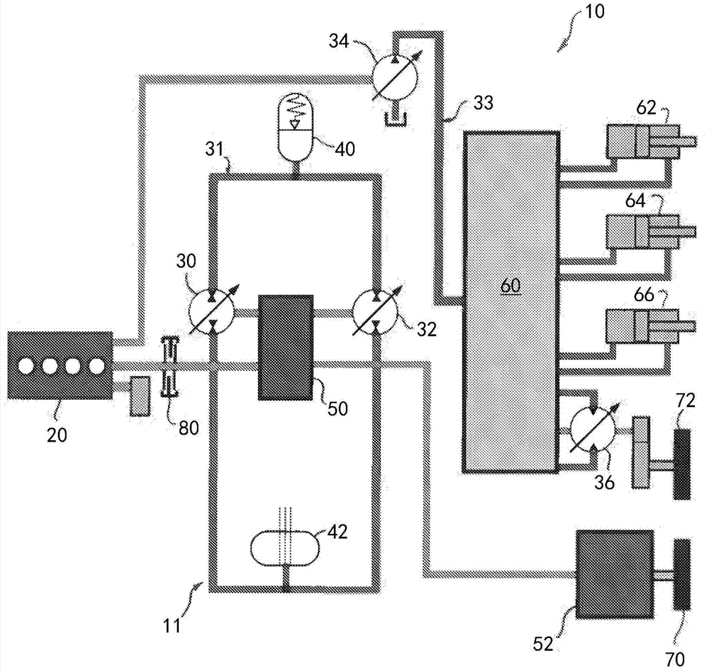
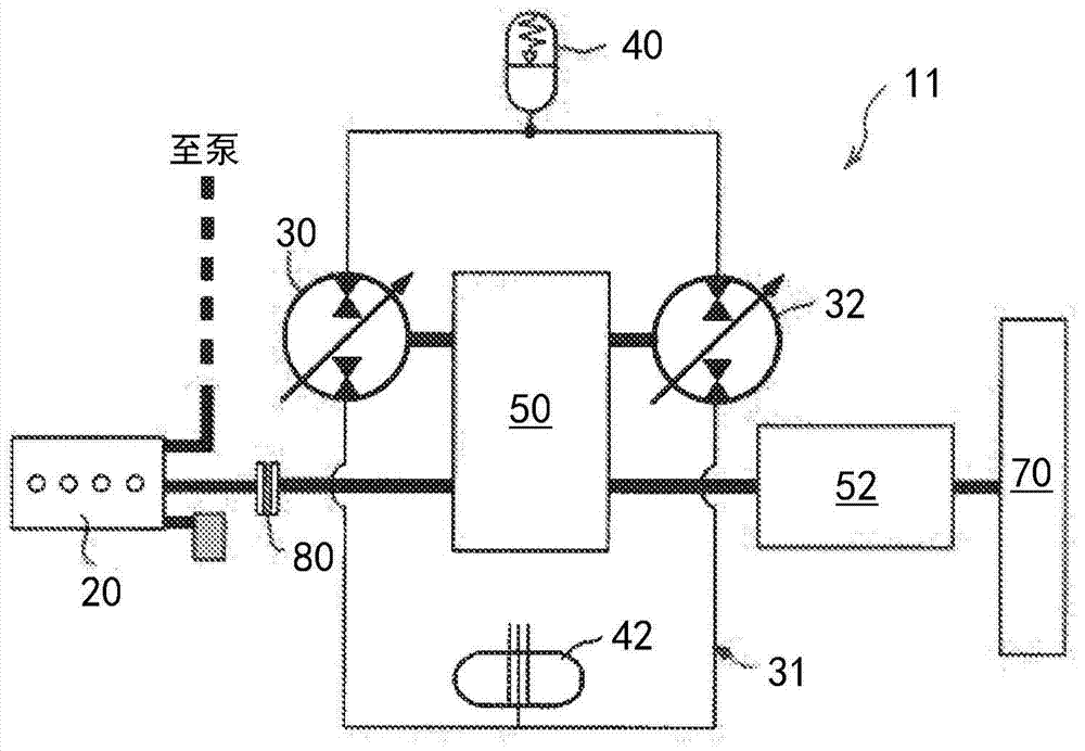
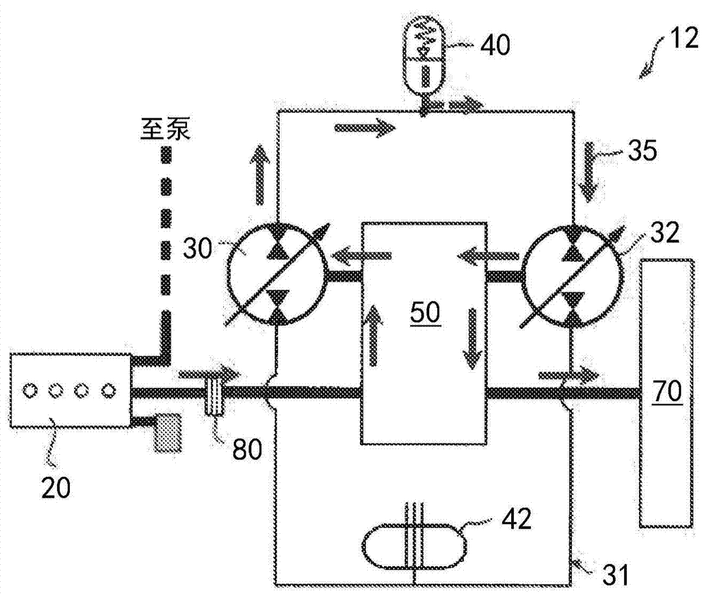
[0021] refer to figure 1 , which shows a hydraulic hybrid drive system 10 for an excavator, the hydraulic hybrid drive system 10 including a hydraulic swing drive system 11 . A hydraulic drive system 10 utilized in an excavator includes the upper structure, chassis, swing, boom, arm and bucket of the excavator (not shown). The hydraulic swing drive system 11 includes a prime mover 20 . Prime mover 20 is preferably an internal combustion (IC) engine, although other prime movers such as gas turbines, electric motors, and fuel cells may also be used. The prime mover 20 is mechanically connected to the first hydraulic unit 30 and the second hydraulic unit 32 , and is mechanically connected to the swing mechanism 70 . The hydraulic units 30, 32 are preferably of the variable displacement type and are reversible, and can function as either pumps or motors, and are referred to herein as hydraulic units or hydraulic pump / motors. By way of example, the hydraulic unit may be an axial...


PUM


Abstract

A swing drive system for an excavator is provided which utilizes a prime mover mechanically connected to a first hydraulic pump / motor and a second hydraulic pump / motor mechanically connected to a swing mechanism. The system includes a hydraulic circuit connecting a hydraulic fluid reservoir, a hydraulic accumulator, the first hydraulic pump / motor, and the second hydraulic pump / motor. The system is operable in one mode where the second hydraulic pump / motor acts as a pump to retard movement of the swing mechanism and pressurized hydraulic fluid from the second hydraulic pump / motor is pumped into the hydraulic accumulator. The system is operable in another mode where the pressurized fluid from the hydraulic accumulator is used to assist the prime mover in driving hydraulic consumers, including the swing drive.

Description

[0001] Cross References to Related Applications [0002] This application claims priority to US Provisional Patent Application No. 61 / 582,862, filed January 4, 2012, the disclosure of which is hereby incorporated by reference in its entirety. technical field [0003] The present invention relates to hydraulic excavators, particularly hydraulic hybrid swing drive systems, which recover energy during swing braking and use the recovered energy to assist a prime mover in powering a swing drive or other functions. Background technique [0004] An excavator is an example of a construction machine that uses multiple hydraulic actuators to accomplish various tasks. These actuators are fluidly connected to a pump that provides pressurized fluid to a cavity within the actuator. The force of this pressurized fluid on the actuator surface causes movement of the actuator and its attached work implement. Once the hydraulic energy is harnessed, the pressurized fluid is expelled from the ...

Claims


Application Information

Patent Timeline
Patent Type & Authority Applications(China)
IPC IPC(8): E02F9/20E02F9/22E02F9/12B66C23/86F15B1/02
CPCE02F9/128E02F9/202E02F9/2217F15B7/003F15B1/024
Inventor 杰夫·卡尔曼张浩理查德·D·金佩尔姜哲生雷蒙德·科利特波格丹·库族尔
Owner PARKER HANNIFIN CORP
Why Eureka
Try Eureka