

Aircraft engine fuel pump bearing flow and associated system and method
An aero-engine and engine technology, which is applied in the direction of engine lubrication, turbine/propulsion fuel delivery system, charging system, etc., and can solve problems such as pressure increase
- Summary
- Abstract
- Description
- Claims
- Application Information
AI Technical Summary
Problems solved by technology
Method used
Image

Examples
Embodiment Construction
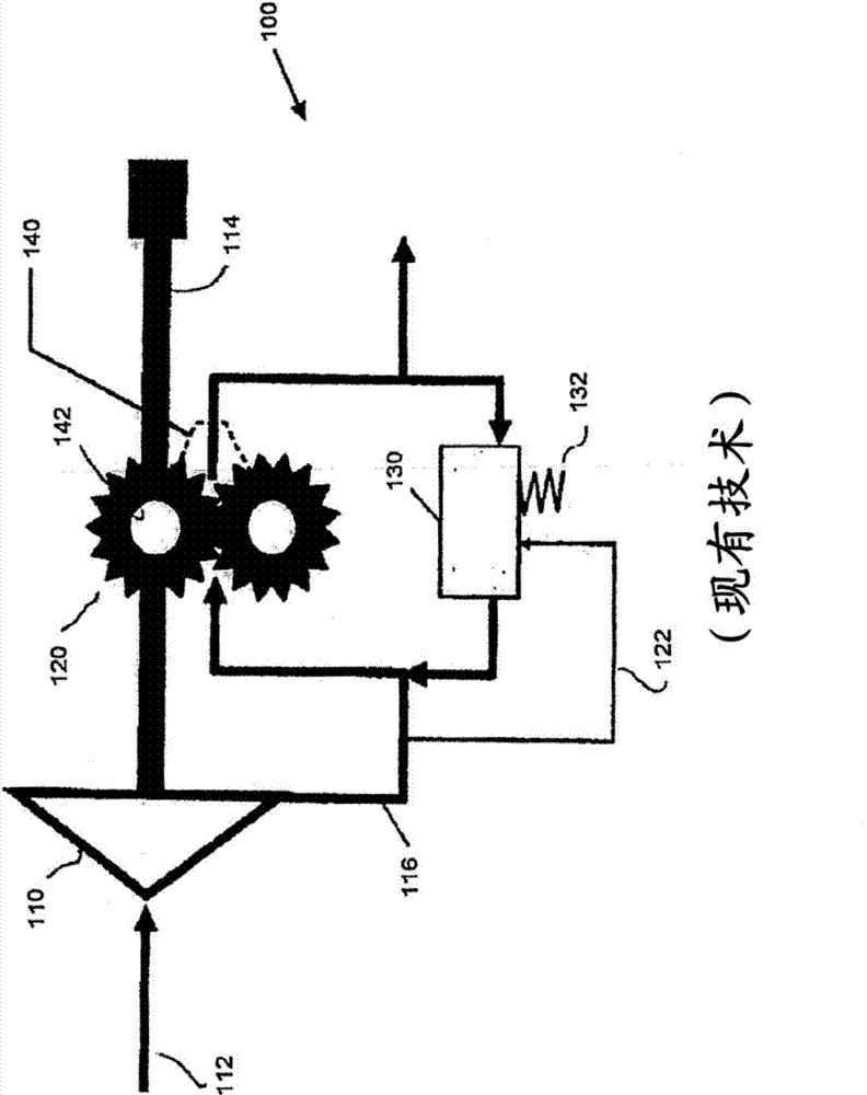
[0027] figure 1 A typical pump that provides a constant supply of bearing lubrication flow to the radial bearings of a pump, such as a high pressure stage pump. More particularly, system 100 includes a first or booster stage pump 110, shown schematically as a centrifugal pump. Fluid enters at 112 to booster stage pump 110 , which is rotated by drive shaft 114 . The output 116 from the boost stage pump 110 is provided to a second or high pressure stage pump 120 downstream of the boost stage. High pressure pump 120 is also driven by shaft 114 . Reference signal 122 is also provided from outlet 116 of booster stage pump 110 to pressure relief valve 130 . Pressure relief valve 130 is biased toward the closed position by means of a biasing member, such as spring 132 . Pressure relief valve 130 receives flow from high pressure pump 120 and if the pressure of the output flow from the high pressure pump provides a force that exceeds the combined signal 122 from booster stage pump ...
PUM
 Abstract
Description
Claims
Application Information