tinted contact lenses

A contact lens and lens technology, applied in glasses/goggles, optics, instruments, etc., can solve problems such as hindering the oxygen permeability of lens raw materials, and achieve the effect of inhibiting deformation

Inactive Publication Date: 2016-08-17
MENICON NECT
View PDF22 Cites 2 Cited by
  • Summary
  • Abstract
  • Description
  • Claims
  • Application Information

AI Technical Summary

Problems solved by technology

The flat design is excellent in the function of changing the appearance of the wearer's pupils, but it is highly likely to hinder the so-called oxygen permeability of the lens material, so it is not necessarily preferable, and it is difficult to change dark pupils with lines or dots the color of the appearance

Method used


Image

  • tinted contact lenses
  • tinted contact lenses
  • tinted contact lenses

Examples


Embodiment 1

[0090] Below, in order to clarify this invention more concretely, several examples are shown.

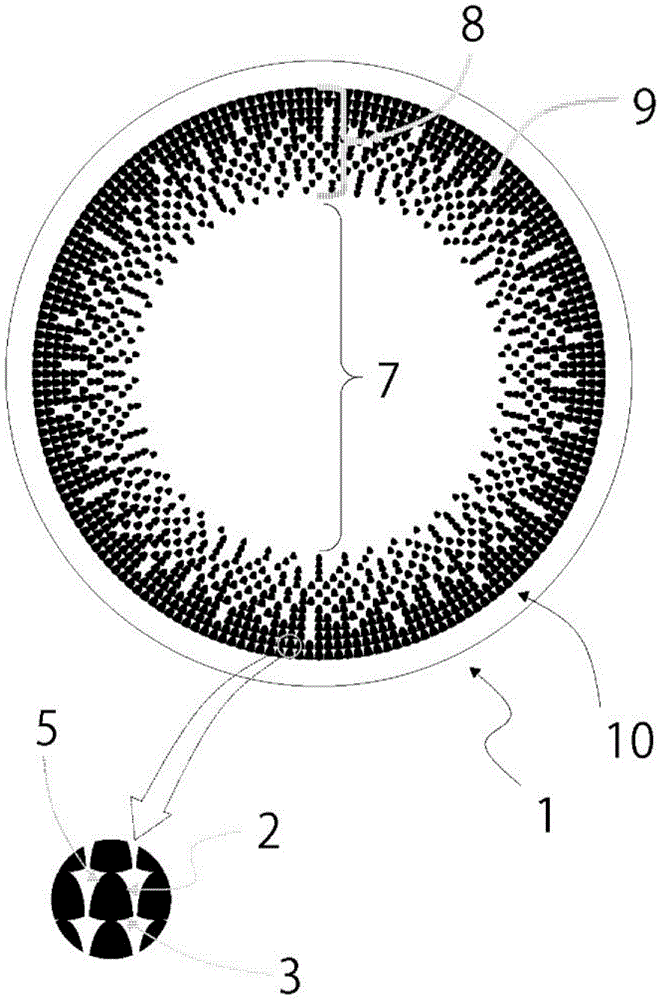
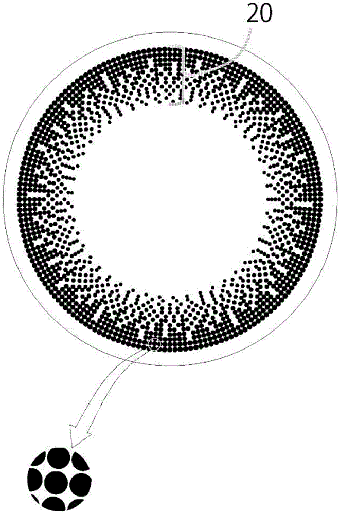
[0091] Apart from figure 1 In addition to the design patterns shown in (Example 1), by image 3 Point (20) shown in (Comparative Example 1), Figure 4 Curve (25) shown in (Comparative Example 2), Figure 5 The rod-shaped (30) shown in (Comparative Example 3), Image 6 (Comparative Example 4) For each design of the annular shape (35), colored contact lenses were produced, and the subjects wore them on one eye, and compared the difference in the appearance of the other eye with the naked eye using a mirror. In addition, the wearing eye was changed, and both eyes were evaluated in the same manner.

[0092] Tinted contact lenses are produced as follows.

[0093]A contact lens forming monomer composition (2-hydroxyethyl methacrylate (hereinafter referred to as 2-HEMA) 59w / w%, glycerin methacrylate ( Hereinafter referred to as GMA) 30w / w%, ethylene glycol dimethacrylate (hereinafter...

Embodiment 2

[0110] In addition to will figure 1 The design pattern becomes Figure 7 ~ Figure 10 Except for the design shown, it carried out similarly to Example 1, and each colored contact lens was produced. Figure 7 ~ Figure 10 All of the designs are examples in which various changes are made to the curvature of the rear end side with respect to the shape of the colored opaque portion, and are linear (13)( Figure 7 , Figure 8 ), the shape curved toward the center of the lens (33)( Figure 9 ), the shape connecting two points on the arc with a straight line (23)( Figure 10 ). It should be noted, Figure 7 and Figure 8 The difference is that, Figure 7 is an example in which the size of the colored opaque portion gradually decreases toward the center of the lens. In contrast, Figure 8 , is an example of not changing the size. For each of these lenses, the same evaluation test as in Example 1 was performed. The results are shown in Table 2.

[0111] 【Table 2】

[0112] ...

Embodiment 3

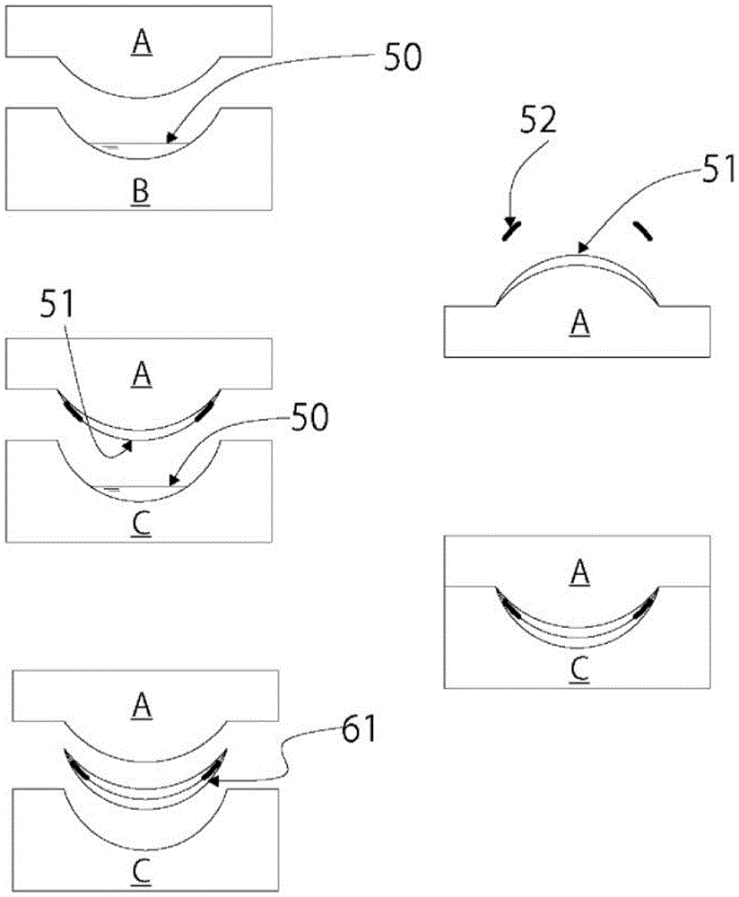
[0115] In the same manner as in Example 1, the concave mold C made of PP was fitted with the convex mold A to carry out polymerization. The concave mold C was filled with 60 µl of the above contact lens-forming monomer composition. In addition, it is designed so that the polymer formed in the concave mold C is thicker than the lens of Example 1. When the female die C is separated from the male die A, the polymer adheres to the male die A. This die was fixed on the shaft of a lathe for contact lens production, and rotated at 300 RPM, and the polymer was cut with a diamond knife, and finished into a contact lens shape. In the same manner as in Example 1, the polymer-adhered punch A finished into a contact lens shape was immersed in 5 ml of purified water, and the same treatment was performed to inspect the polymer. Based on PW: -3.00D, CT: 0.11mm, and diameter: 14.2mm, there is a figure 1 tinted contact lenses with a scale pattern.


PUM


Abstract

The present invention proposes a design that can objectively change the original color and texture while imparting a natural appearance to the pupils of the contact lens wearer. A colored contact lens that suppresses an increase in manufacturing cost. The colored contact lens of the present invention is a colored contact lens having a transparent central vision area and a colored area surrounding it, wherein the colored area forms a continuous transparent portion substantially as a sea portion, and an island as an island. A sea-island structure composed of partially discontinuous colored opaque parts, the colored opaque part has a scale shape, and has a size of 70-600 μm in the radial direction of the lens and 40-300 μm in the circumferential direction of the lens.

Description

technical field [0001] The present invention relates to a colored contact lens having a color pattern capable of imparting a very natural appearance and changing the appearance of the wearer's pupil. Background technique [0002] Tinted contact lenses are not so much used for vision correction as cosmetics, and soft contact lenses are sold as the mainstream (some are also artificial for cosmetic purposes for patients with abnormal irises and corneas of glasses). example for ophthalmic use, which also sells hard contact lenses). [0003] In the past, colored contact lenses were not subject to restrictions under the Pharmaceutical Affairs Law unless they were intended for vision correction. Therefore, we have received reports of health damage due to product completion, sales / use instructions, etc., and as a response to the administrative department, we have strengthened the policy of restricting within the scope of the Pharmaceutical Affairs Law, November 4, 2009 It will be ...

Claims


Application Information

Patent Timeline
Patent Type & Authority Patents(China)
IPC IPC(8): G02C7/04
CPCG02C7/046
Inventor 横田知章
Owner MENICON NECT
Why Eureka
Try Eureka