End face grinding device of chain wheel

A sprocket and end face technology, which is applied in the direction of grinding machines, grinding workpiece supports, grinding/polishing equipment, etc., can solve the problems of long time consumption, increased operation difficulty, time consumption, and affecting the use of sprockets, so as to achieve saving Effect of setup time and machining time

Inactive Publication Date: 2014-12-31
池州市维大茵特机械有限公司
View PDF6 Cites 4 Cited by
  • Summary
  • Abstract
  • Description
  • Claims
  • Application Information

AI Technical Summary

Problems solved by technology

[0002] The existing die-casting sprocket technology, due to the complex structure of the casting itself, many tooth shapes, and the improper control of the pressure and unstable adjustment of the mold temperature during the die-casting process, will lead to the appearance of air bubbles on the end face of the sprocket produced. These problems will affect the use of the sprocket. The traditional end face processing method is to use a large water mill for end f

Method used


Image

  • End face grinding device of chain wheel
  • End face grinding device of chain wheel
  • End face grinding device of chain wheel

Examples


Embodiment Construction

[0026] In the following, numerous specific details are set forth in order to provide a thorough understanding of the concepts underlying the described embodiments. It will be apparent, however, to one skilled in the art that the described embodiments may be practiced without some or all of these specific details. In other instances, well known processing steps have not been described in detail.

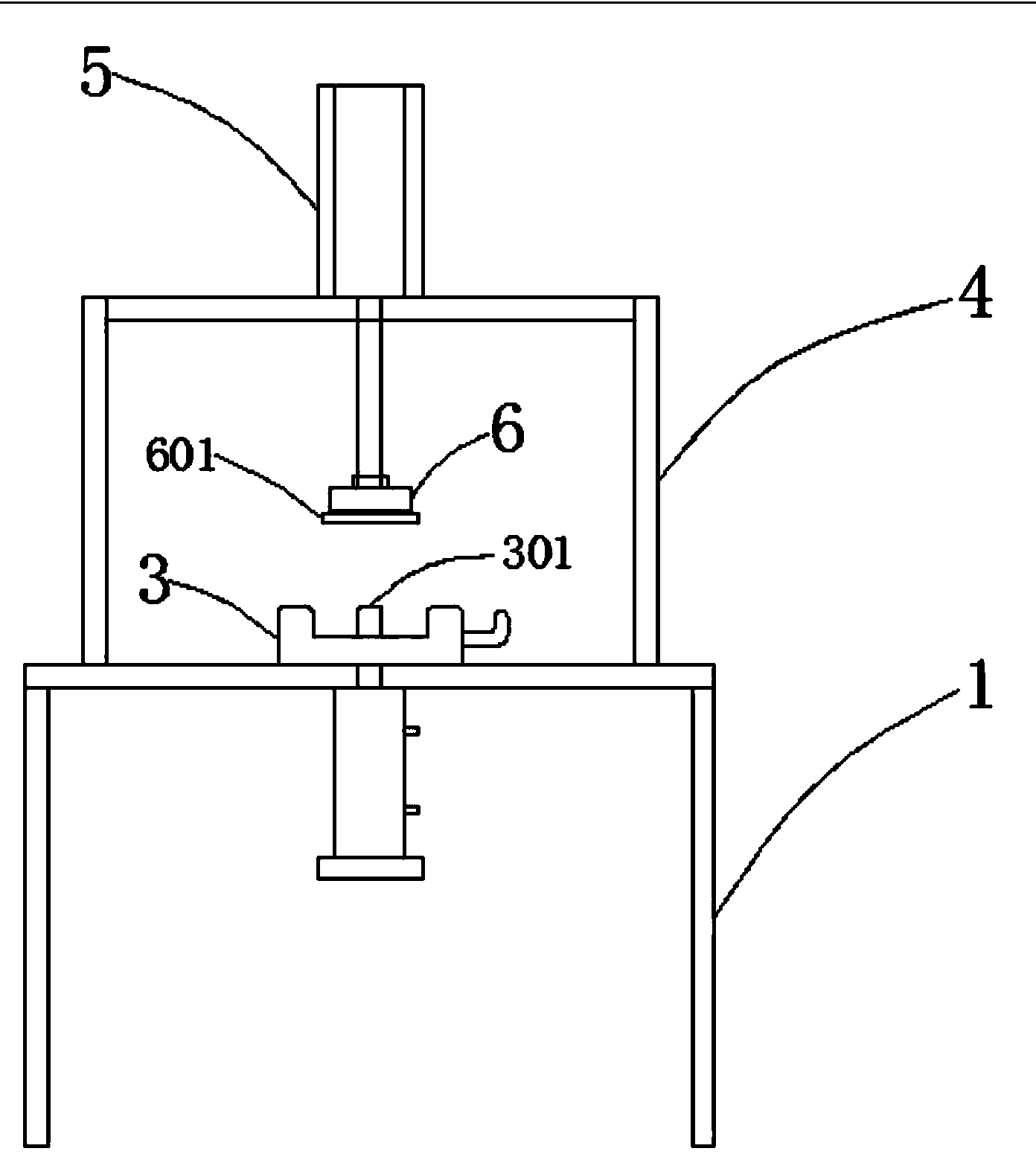
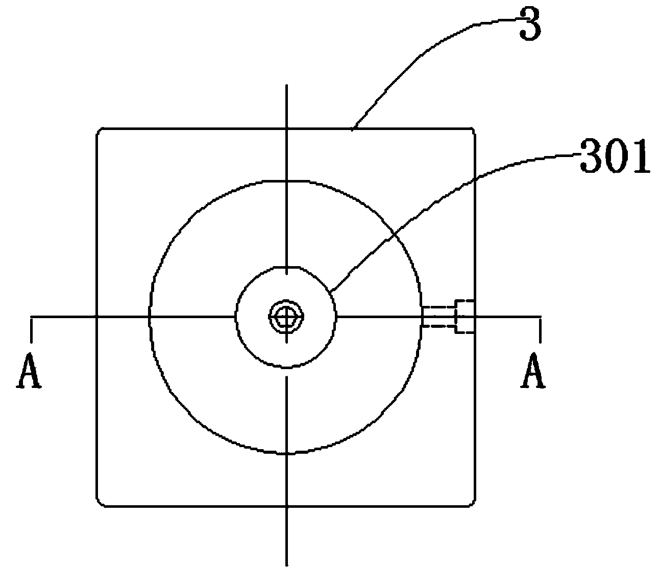
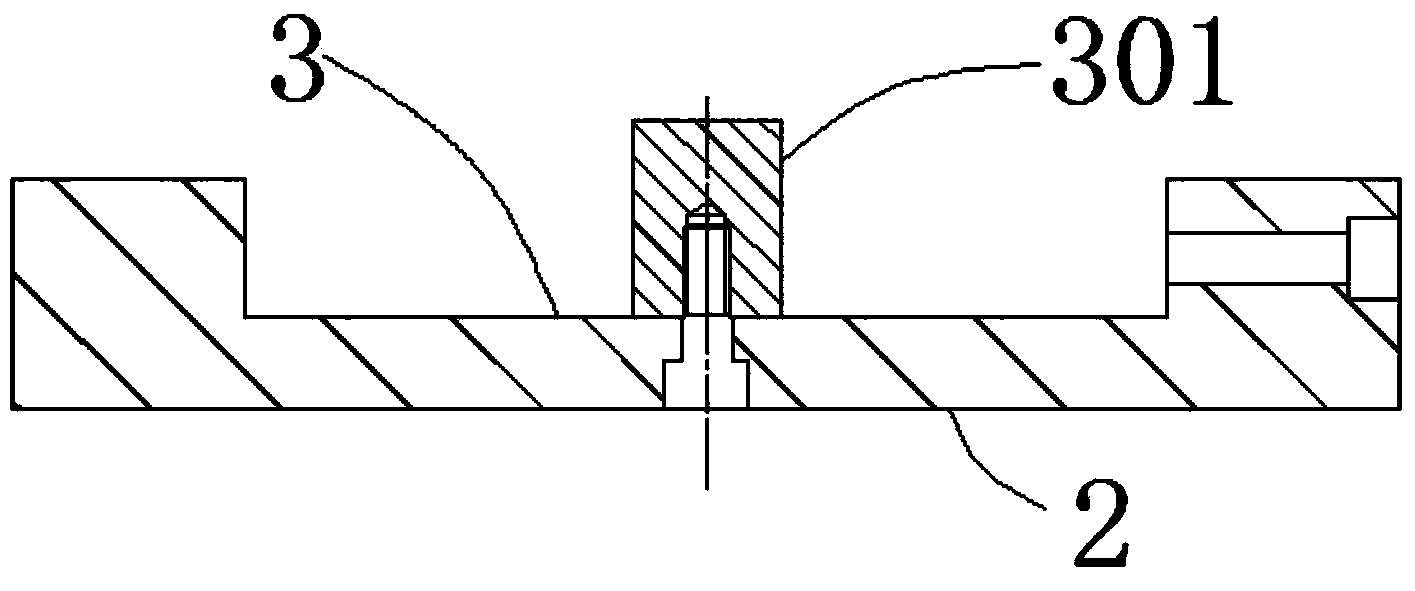
[0027] Such as figure 1 , figure 2 , image 3 As shown, it includes a frame 1, a cylinder 2, a sprocket placement plate 3, a motor frame 4, a motor 5, and a suction cup 6. The sandpaper 601 is adhered to the suction cup 6 through the action of felt, and the cylinder 2 is fixed by screws. In the lower part of the sprocket placement plate 3, the sprocket placement plate 3 is fixed on the upper end face of the frame by means of screw locking, and is located at the bottom of the sprocket placement locking device. On the frame 1, the motor 5 is fixedly connected to the motor frame 4 b...


PUM


Abstract

The invention discloses an end face grinding device of a chain wheel. The end face grinding device comprises a rack, wherein a chain wheel placing and locking device is arranged above the rack; the end face of the upper part of the rack is provided with a motor frame; the transverse end face of the motor frame is provided with a motor. Compared with the prior art, the overall rough end face of the chain wheel caused by various reasons is ground and finished at one time through the end face grinding device without repeated clamping, repairing of a grinding wheel or longitudinal movement grinding, the grinding can be performed by just clamping the chain wheel in a chain wheel placing plate, turning a locking handle and starting a cylinder and the motor, and the entire plane is ground at one time, so that the clamping time and the machining time are saved.

Description

technical field [0001] The invention relates to a grinding device, in particular to an end face grinding device of a chain wheel. Background technique [0002] The existing die-casting sprocket technology, due to the complex structure of the casting itself, many tooth shapes, and the improper control of the pressure and unstable adjustment of the mold temperature during the die-casting process, will lead to the appearance of air bubbles on the end face of the sprocket produced. These problems will affect the use of the sprocket. The traditional end face processing method is to use a large water mill for end face processing. The sprocket needs to be placed on the workbench and slowly lowered, moving back and forth for processing, which takes a long time. It is necessary to modify the shape of the grinding wheel frequently, and the material of the sprocket in the present invention is ADC12, which does not have magnetism and needs to be fixed on the workbench of the grinding ma...

Claims


Application Information

Patent Timeline
IPC IPC(8): B24B7/16B24B41/06
CPCB24B7/16B24B41/067
Inventor 胡章华
Owner 池州市维大茵特机械有限公司
Why Eureka
Try Eureka