
Double-cushion airbag shock absorber

A shock absorber, double buffer technology, applied in the direction of shock absorber, gas-liquid shock absorber, spring/shock absorber, etc. It can overcome the problems such as severe vibration of the vehicle and the body, and achieve the effect of overcoming the flow to fill the lag defect, eliminating the hidden danger of empty travel, and prolonging the overall life.

Inactive Publication Date: 2014-12-31
丁小双
View PDF1 Cites 1 Cited by
  • Summary
  • Abstract
  • Description
  • Claims
  • Application Information

AI Technical Summary

Problems solved by technology

Chinese patent, the patent number is 200620141855.7, the patented technology named "Cylinder Hydraulic Shock Absorber with Floating Piston", a floating piston device is installed at the bottom of the cylinder, which basically solves the above problems, but this technology still has shortcomings, If the volume filled with high-pressure gas is too small, it cannot be used for shock absorbers with large connecting rods
However, this "tubular hydraulic shock absorber with floating piston" still has drawbacks
That is, due to the limitation of the space of the shock absorber, the floating piston device installed at the bottom of the cylinder has a small volume. Regulatory effect is limited
That is to say, its adjustment amount is small, and it is only suitable to be installed on the shock absorber of small vehicles to play its role, and cannot meet the needs of large shock absorbers.
In addition, the existing shock absorber generally has a shortcoming. Since the working cylinder is cylindrical, the connecting rod piston can only perform one level of buffering when buffering the hydraulic pressure, so the buffering force is insufficient, and it is easy to cause severe vibration of the vehicle body.

Method used


Image

  • Double-cushion airbag shock absorber

Examples


Embodiment Construction

[0011] The present invention will be further described below in conjunction with the embodiments with reference to the accompanying drawings.

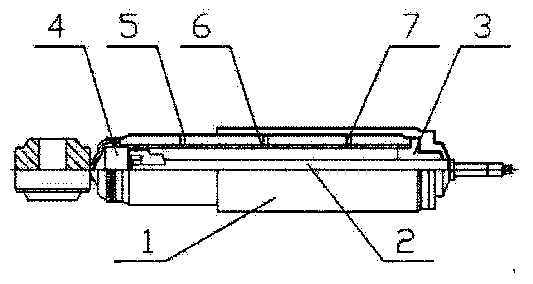
[0012] Such as figure 1 As shown, a double-buffer airbag shock absorber includes a shock absorber main body, a piston rod, an oil guide, a piston assembly and an oil storage cylinder, an oil storage cylinder is arranged in the working cylinder of the shock absorber main body, and the piston The rod is inserted into the oil storage cylinder, the piston assembly is arranged at the tail end of the piston rod, the oil guide is arranged at the upper end of the oil storage cylinder, and the working cylinder is composed of the first cylinder and the second cylinder with different diameters. body, a transition section is provided between the first cylinder and the second cylinder, the surface of the body of the piston rod is provided with a helically arranged oil groove, and the bottom of the oil storage cylinder is provided with a cylindrical...


PUM


Abstract

The invention discloses a double-cushion airbag shock absorber. The double-cushion airbag shock absorber comprises a shock absorber body, a piston rod, an oil deflector, a piston component and an oil storage tank, wherein the oil storage tank is arranged in a working cylinder of the shock absorber body; the piston rod is inserted into the oil storage tank; the piston component is arranged at the tail end of the piston rod; the oil deflector is arranged at the upper end of the oil storage tank; the working cylinder comprises a first cylinder body and a second cylinder body with different diameters; a transition section is arranged between the first cylinder body and the second cylinder body; an oil groove which is arranged in a helix way is arranged on the surface of a tube body of the piston rod body; a cylindrical airbag is arranged at the bottom of the oil storage tank; the airbag is filled with inert gas; a high-pressure airbag adjusting device is arranged on the cylindrical airbag. Compared with the prior art, the double-cushion airbag shock absorber has the advantages that the shock absorber can perform double-cushion shock absorption, has good shock absorption performance and a simple structure, and can be applied to various work environments, and particularly to oversize vehicles.

Description

technical field [0001] The invention relates to a vehicle shock absorber which improves the stability of the vehicle during running, in particular to a double-buffer airbag shock absorber. Background technique [0002] At present, the shock absorbers used in automobiles are basically hydraulic shock absorbers. When the vehicle is running in bumps, the piston rod of the hydraulic shock absorber continues to expand and contract in the cylinder body, and the shock absorber oil in the cylinder body continuously flows up and down through the valve plate in the valve body to buffer the impact force and reduce the bump. Because the cylinder volume is reduced when the piston rod is stretched into the cylinder, the cylinder cannot be filled with damping oil completely. Because of the damping oil in the cylinder can not be filled originally, the shock absorber also inevitably occurs oil leakage and other factors during use to cause oil loss, and the damping oil in the cylinder will b...

Claims


Application Information

Patent Timeline
Patent Type & Authority Applications(China)
IPC IPC(8): F16F9/08F16F9/32
Inventor 丁小双
Owner 丁小双
Learn More