Pulse damper using composite spring

A technology of pulsation damper and composite spring, applied in the direction of engine components, machines/engines, liquid fuel feeders, etc., can solve the problem of difficult to control pulsation in a wide pressure range, loss of spring recovery force and spring performance, and difficulty in dealing with spring plasticity Deformation and other problems can be improved to achieve the effect of improving operability, no energy loss, and reducing noise

Inactive Publication Date: 2014-12-31
黄炳灿
View PDF5 Cites 5 Cited by
  • Summary
  • Abstract
  • Description
  • Claims
  • Application Information

AI Technical Summary

Problems solved by technology

However, the existing pulsation damping device using an orifice is a method of rapidly reducing the cross-sectional area of ​​the fuel pipe to generate flow and pressure resistance to attenuate the pulsation wave.
The existing orifice method utilizes the flow rate and pressure resistance, so it is a structure with a large loss of pump energy.
[0011] In addition, there is also a pulsation damper that uses a single coil spring as described in the past, such as patent application No. 10-2007-0070249, but the above technology uses a single coil spring, so it is difficult to control Disadvantages of pulsation over a wide pressure range
[0012] Moreover, once all springs exceed the elastic limit, they will be plastically deformed and lose spring recovery force and spring performance. Therefore, in order to prevent plastic deformation, a stop device that stops the action with a load above the elastic region is required, and the structure of the above-mentioned patent technology is not A construction without said stop, which makes it difficult to cope with the plastic deformation of the spring

Method used


Image

  • Pulse damper using composite spring
  • Pulse damper using composite spring
  • Pulse damper using composite spring

Examples


Embodiment Construction

[0026] Hereinafter, preferred embodiments of the present invention will be described in detail with reference to the accompanying drawings.

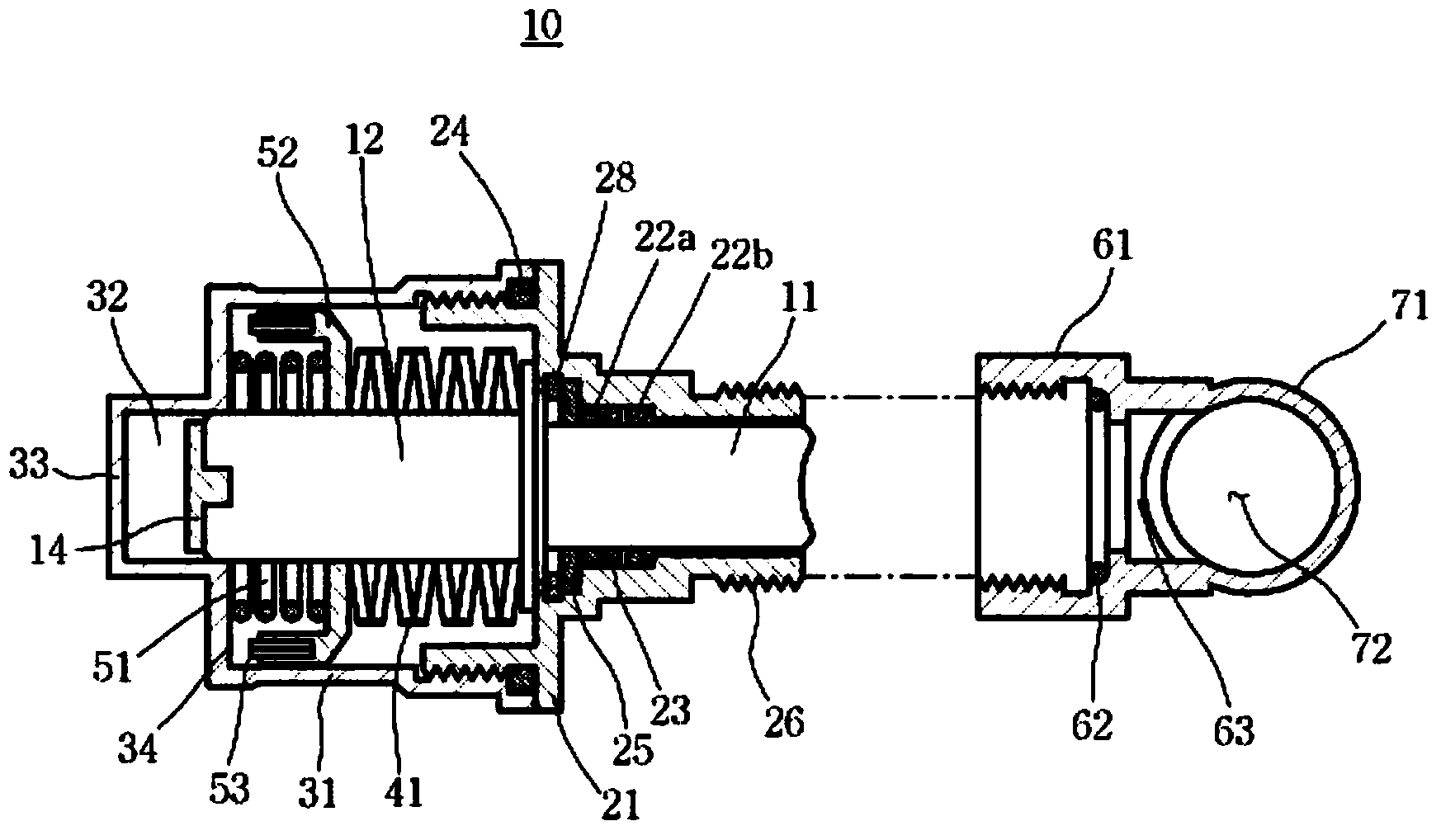
[0027] figure 1 A pulsation damper according to an embodiment of the present invention is shown in a longitudinal sectional view.

[0028] Such as figure 1 As shown, the pulsation damper 10 of the composite spring according to the present invention is composed of a main body 21, a spring body 31, and a connector 61, wherein the main body 21 has a built-in piston 11 capable of rectilinear reciprocating motion, and the spring body 31 and the above-mentioned main body 21 Screwed together, the connector 61 is screwed together with the above-mentioned main body 21 .

[0029] The above-mentioned connector 61 is integrally formed with a fuel rail pipe 71, and the fuel rail pipe 71 is connected to a plunger pump (not shown) for fuel supply of a gasoline direct injection engine, and a connecting passage 63 is formed inside the above-mentioned c...


PUM


Abstract

The present invention relates to a pulse damper using a composite spring device for eliminating pulse waves in a plunger pump for supplying fuel so as to maintain the fuel pressure at a constant level without energy loss and to cover a wide range of pressure, which comprises a spring body (31), and a body (21) for receiving an O-ring spacer (23) supported by an internal O-ring cap (25), wherein a low pressure coil spring (51) and a high pressure disk spring (41) are arranged in a line inside the spring body (31) so that the low pressure coil spring (51) primarily works and then stops by making a low pressure spring cover (52) and a low spring pad (53) contact a low pressure spring stopper (34), and secondarily the high pressure disk spring (41) works and then stops by making a high pressure spring pad (14) mounted on one end of a spring guide shaft (12) connected to a piston (11); contact a high pressure spring stopper (33).

Description

technical field [0001] The present invention relates to a kind of pulsation damper suitable for gasoline direct injection engine, more specifically, relates to a kind of pulsation damper utilizing composite spring, the pulsation damper utilizing composite spring is attached to gasoline direct injection The main body of the pulsation damper of the fuel rail of the engine can perform linear reciprocating motion. The piston uses the composite spring to repeatedly convert the pulsation wave in the fuel into compression energy (Energy) and store and release it, eliminating the need for a plunger pump (plunger pump) for fuel supply. The pulsation waves generated by the pump) make the fuel maintain a certain pressure state without pulsation waves, so that it can be used without engine pump loss. Background technique [0002] In general, an engine of a vehicle is configured such that fuel stored in a fuel tank is supplied at high pressure by a fuel pump to an injector that injects t...

Claims


Application Information

Patent Timeline
Patent Type & Authority Applications(China)
IPC IPC(8): F02M55/04F02M55/02
CPCF02M55/02F02M55/04F02M63/0265F02M2200/31F02M2200/315F02M37/0041
Inventor 黄炳灿
Owner 黄炳灿
Why Eureka
Try Eureka