Artificial hand

A prosthetic hand and finger technology, which is applied in the field of prosthetic hands, can solve the problems of less movement of fingers to grasp objects, failure to ensure good signal, and heavy quality of prosthetic hands, etc., to achieve large grip, improve commercialization potential, and low processing costs.

Active Publication Date: 2015-01-07
SHENZHEN INST OF ADVANCED TECH CHINESE ACAD OF SCI
View PDF8 Cites 6 Cited by
  • Summary
  • Abstract
  • Description
  • Claims
  • Application Information

AI Technical Summary

Problems solved by technology

[0010] (1) The number of motors is large, and the cost of the micro-motors used is relatively high, and the quality of the prosthetic hand is heavy
[0011] (2) For a prosthetic hand that uses a link transmission mechanism to realize finger movement, the fingers have fewer movements to grasp objects, and the practicability is not strong
[0012] (3) Multi-signal input is required to complete precise grasping, which requires hi

Method used


Image

  • Artificial hand
  • Artificial hand
  • Artificial hand

Examples


Embodiment 1

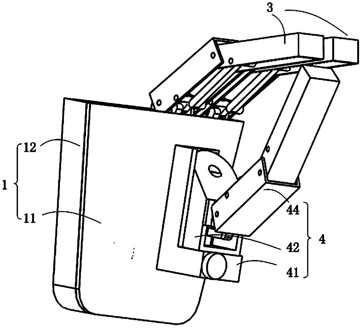
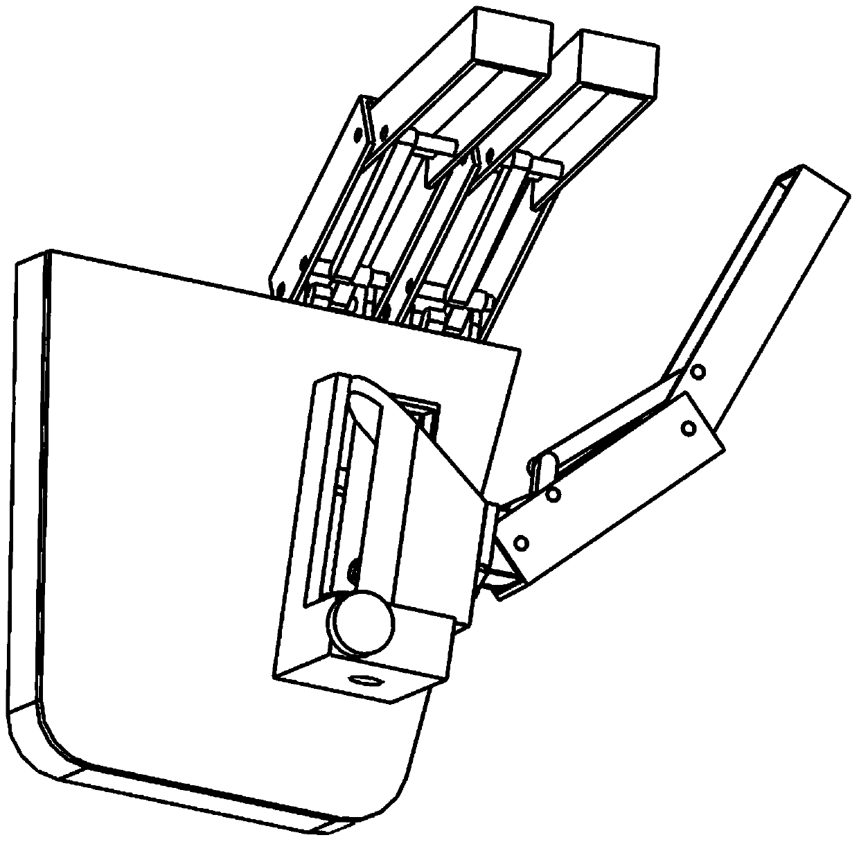
[0060] refer to figure 1 Referring to FIG. 6 , this embodiment provides a prosthetic hand, including a palm body 1 , a driving unit 2 , a finger unit 3 and a thumb unit 4 .

[0061] Such as figure 1 As shown, the palm body 1 includes two opposite palm covers 11 and a side cover 12 connecting the two palm covers 11 . The palm body 1 is a cavity enclosed by the two palm covers 11 and the side covers 12 .

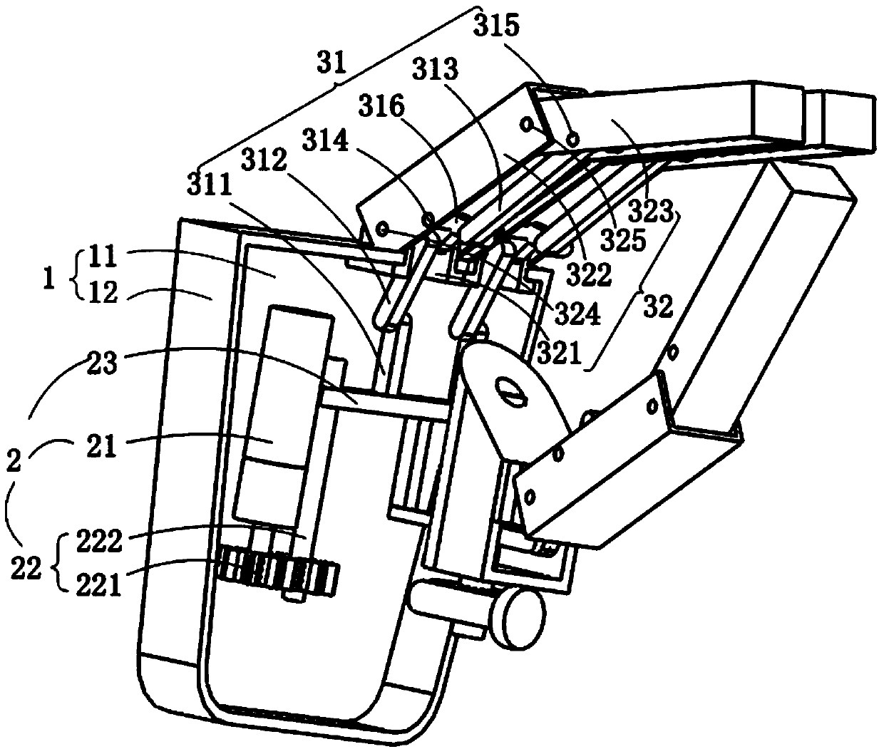
[0062] Such as image 3 As shown, the drive unit 2 is arranged in the palm body 1 and includes a drive motor 21, a transmission mechanism 22 and a drive plate 23. The two ends of the transmission mechanism 22 are respectively connected to the drive motor 21 and the drive plate 23. The motor, that is, the drive motor 21 is actually a geared motor 21 .

[0063] The geared motor 21 is vertically arranged in the palm body 1, and the geared motor 21 is an improved motor integrated with a motor and a reducer. Adopting this motor can make the overall structure of the prosthetic ha...

Embodiment 2

[0092] Such as Figure 7 As shown, the difference between this embodiment and Embodiment 1 is that in this embodiment, the finger transmission mechanism 31 also includes a fourth finger transmission rod 317 and a fifth finger connecting piece 318, and the finger structure 32 also includes a third finger knuckle 326. The sixth finger connector 327;

[0093] One end of the fourth finger transmission rod 317 is connected with the third finger transmission rod 313, and the other end is connected with the third finger knuckle 326 through the fifth finger connector 318, and the third finger knuckle 326 is connected with the second finger connector 327 through the sixth finger connector 327. Finger knuckles 323 are connected.

Embodiment 3

[0095] The difference between this embodiment and Embodiment 1 is that the geared motor in this embodiment is arranged horizontally, and no synchronous gear is included in the drive mechanism of the drive unit. The drive unit includes a geared motor, a screw and a drive plate. The two ends of the rod are respectively connected to the geared motor and the driving board.

[0096] When the geared motor works, the geared motor drives the screw to move, and then the screw drives the drive plate to move.


PUM


Abstract

The invention relates to an artificial hand. The artificial hand comprises a palm main body, a driving unit, finger units and a thumb unit, wherein the driving unit is arranged in the palm main body, and comprises a reducing motor, a transmission mechanism and a driver board; the finger units and the thumb unit realize finger flexion and extension through link structures and a hinge connection mode; the thumb unit realizes adduction and abduction of a thumb through a worm and worm gear meshing transmission mechanism. According to the invention, flexion and extension of three fingers can be realized only through one motor, so that compared with an artificial hand with multiple motors, the artificial hand is lighter. Moreover, as the link structures which are relatively low in machining cost are mainly used for movement of the fingers, the cost of the artificial hand is lowered, and the artificial hand better meets the requirements of consumers. In addition, as the driving parts are all arranged in the cavity of the palm, movement of the wrist is not influenced. The artificial hand provided by the invention can perform various frequently used movements in daily life, so that the practicability is enhanced.

Description

technical field [0001] The invention relates to the field of medical instruments, in particular to a prosthetic hand. Background technique [0002] At present, the number of amputees caused by various natural disasters and accidents continues to rise. In view of the various life pressures they are currently facing, many amputees hope to choose to wear artificial limbs to complete some corresponding actions and improve their employability. It was reported in foreign literature in 2005 that in the online questionnaire, people wearing prosthetic hands were investigated, and daily life force grasping accounted for 35%, precise pinching accounted for 30%, side pinching accounted for 20%, other actions such as index finger extension , hook grip, etc. are also widely used, so the research direction of artificial prosthetic hands is gradually developing towards commercialization, and it is expected to be able to complete common actions in daily life while having the characteristics ...

Claims


Application Information

Patent Timeline
IPC IPC(8): A61F2/56
Inventor 匡星王子儒郑悦李光林
Owner SHENZHEN INST OF ADVANCED TECH CHINESE ACAD OF SCI
Why Eureka
Try Eureka