
Turbine high pressure inner cylinder thermometer hole machining location device and use method thereof

A technology of positioning device and temperature measuring hole, applied in the field of positioning device for processing temperature measuring hole, can solve problems such as dislocation, and achieve the effect of low manufacturing cost and simple structure

Active Publication Date: 2015-01-07
HARBIN TURBINE
View PDF6 Cites 2 Cited by
  • Summary
  • Abstract
  • Description
  • Claims
  • Application Information

AI Technical Summary

Problems solved by technology

[0003] The purpose of the present invention is to solve the problem that the positions of the temperature measuring hole of the high pressure inner cylinder of the steam turbine and the through hole of the outer cylinder are easily misaligned after processing, and provide a positioning device for processing the temperature measuring hole of the high pressure inner cylinder of the steam turbine and its application method

Method used


Image

  • Turbine high pressure inner cylinder thermometer hole machining location device and use method thereof
  • Turbine high pressure inner cylinder thermometer hole machining location device and use method thereof
  • Turbine high pressure inner cylinder thermometer hole machining location device and use method thereof

Examples


specific Embodiment approach 1

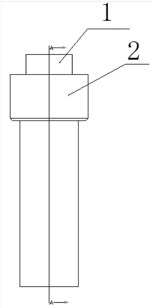
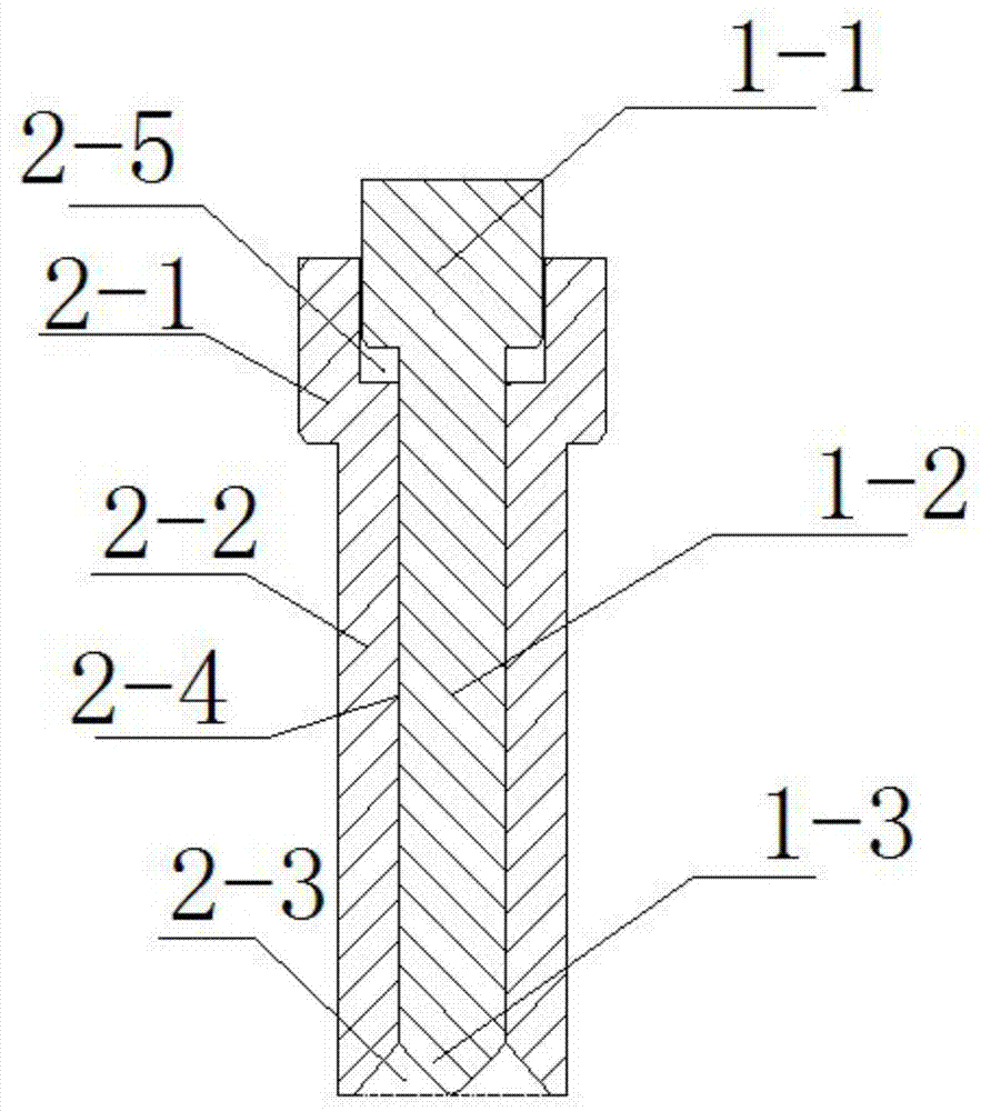
[0019] Specific Embodiment 1: A positioning device for machining the temperature measuring hole of the high-pressure inner cylinder of a steam turbine according to this embodiment is composed of a stepped shaft 1 and a reducing tube 2, wherein the stepped shaft 1 is divided into a cylinder 1 from top to bottom -1, three parts of cylinder 1-2 and cone 1-3, the reducing tube 2 is divided into three parts of flared tube 2-1, straight tube 2-2 and tapered hole tube 2-3 from top to bottom; The cylinder 1-2 has a smaller diameter than the cylinder 1-1.

specific Embodiment approach 2

[0020] Embodiment 2: This embodiment is the same as Embodiment 1 in that: the outer diameter of the straight pipe 2-2 is the same as the diameter of the through hole of the high-pressure outer cylinder 3 of the steam turbine. Others are the same as in the first embodiment.

[0021] The outer diameter of the straight pipe 2-2 and the diameter of the through hole of the high-pressure outer cylinder 3 are operated in cooperation with the shaft hole.

specific Embodiment approach 3

[0022] Specific embodiment three: a method for using a positioning device for processing a temperature measuring hole in a high-pressure inner cylinder of a steam turbine according to this embodiment is characterized in that it is carried out in accordance with the following steps:

[0023] 1. Assemble the high-pressure outer cylinder 3 and the high-pressure inner cylinder 4 of the steam turbine according to the position requirements in the assembly process;

[0024] 2. Paint the end face side of the tapered hole tube 2-3 for marking;

[0025] 3. Insert the reducing tube 2 into the through hole of the high-pressure outer cylinder 3 until the tapered hole tube 2-3 of the reducing tube 2 touches the temperature-measuring hole surface 5 of the high-pressure inner cylinder 4; then insert the stepped shaft 1. Insert it into the reducing tube 2 until the cone 1-3 of the stepped shaft 1 touches the surface 5 of the temperature measuring hole of the high-pressure inner cylinder 4;

...


PUM


Abstract

The invention provides a turbine high pressure inner cylinder thermometer hole machining location device and a use method thereof. The location device and the use method solve the problem that a thermometer hole of a high pressure inner cylinder and a through hole of an outer cylinder of the turbine can be staggered easily after being machined. The location device is formed by a stepped shaft and a reducer, the reducer is inserted into the through hole of the high pressure outer cylinder, and then the stepped shaft is inserted into the reducer. After an annular stamp on the thermometer hole lug face of the high pressure inner cylinder is formed by the pigment spread on the end face of a conical hole pipe of the reducer, and machining can be conducted according to the stamp. The location device can ensure the machining position, effectively ensures the machined holes of the outer cylinder (to prevent galling) and is simple in structure and low in manufacture cost.

Description

technical field [0001] The invention relates to a positioning device for temperature measuring hole processing and a using method thereof. Background technique [0002] The internal working state of the steam turbine unit is high temperature and high pressure. Because the temperature and pressure need to be monitored, there are a series of sensors for temperature measurement and pressure measurement in the components. In the cylinder wall of the inner cylinder, the through hole of the outer cylinder and the blind hole and through hole of the inner cylinder must have positional requirements. In the past, the two holes were often misaligned when processed separately according to the drawing, and the temperature measuring tube could not be smoothly inserted through the through hole of the outer cylinder. Inserting the temperature measuring hole of the inner cylinder, how to ensure the positional accuracy of the temperature measuring hole of the high pressure inner cylinder and ...

Claims


Application Information

Patent Timeline
Patent Type & Authority Applications(China)
IPC IPC(8): B23B47/00B25H7/04
CPCB23B49/00B25H7/04
Inventor 马铭阳罗小明冯帆夏元峰于明哲李久雷郁洪光张德宇张久鑫王其江
Owner HARBIN TURBINE
Learn More