
Vertical condenser

A condenser and vertical technology, which is applied in the field of new high-efficiency vertical condensers, can solve the problems of reducing heat exchange efficiency, achieve high heat exchange efficiency, reduce gas pressure drop, and save equipment footprint

Inactive Publication Date: 2015-01-07
ATHCO ENG SHANGHAI CO LTD
View PDF6 Cites 6 Cited by
  • Summary
  • Abstract
  • Description
  • Claims
  • Application Information

AI Technical Summary

Problems solved by technology

For the form of heat exchanger, the conventional shell and tube type is horizontal, which reduces the heat exchange efficiency in form

Method used


Image

  • Vertical condenser
  • Vertical condenser
  • Vertical condenser

Examples


Embodiment

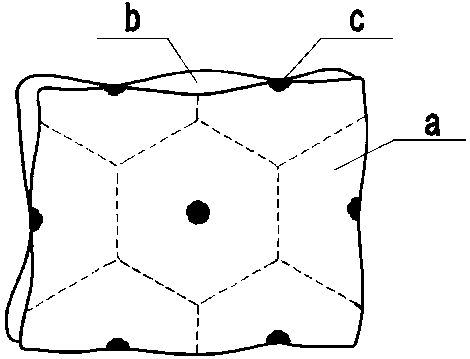
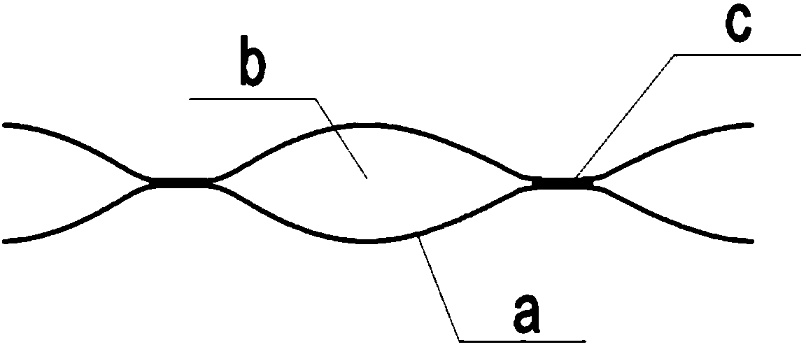
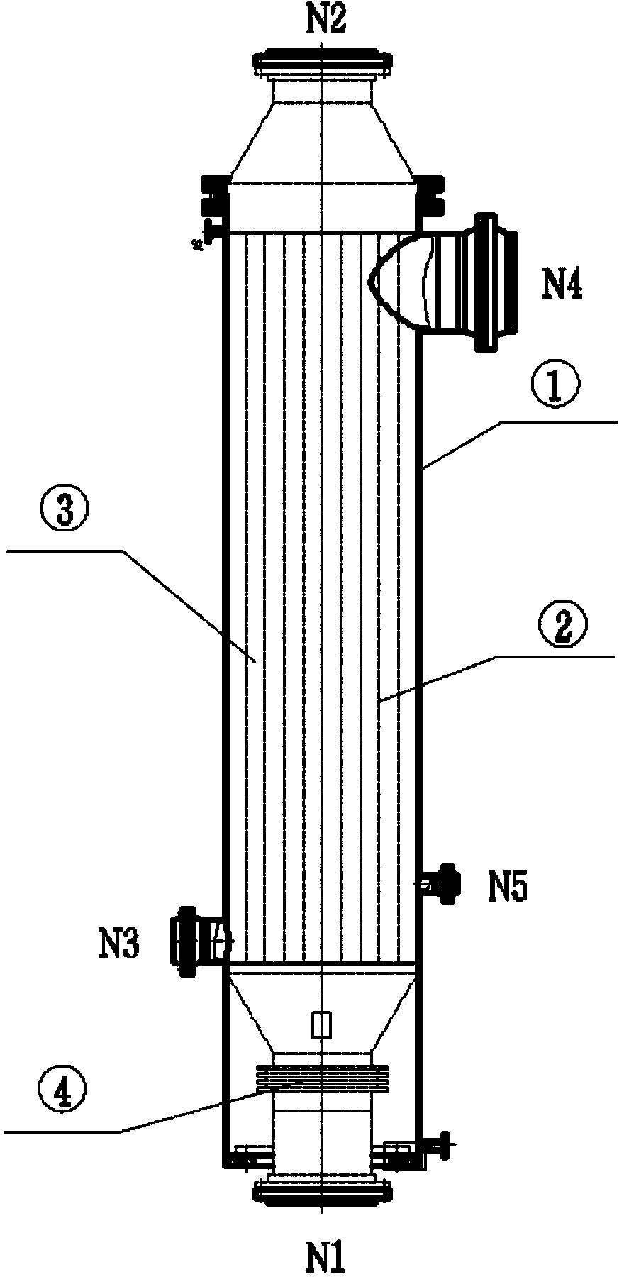
[0041] like Figure 1~3 As shown, a vertical condenser, the condenser includes a pair of heat exchange plates ②, an expansion joint ④ and a shell ①, the heat exchange plate pair is formed by two metal plates through multi-point welding and can be replaced As for the components of the plate-side cavity b through which the thermal fluid circulates, multiple pairs of heat-exchanging plate pairs are installed in the shell, and a shell-side cavity ③ is formed between each pair of heat-exchanging plate pairs and between the shell and the shell. A plurality of welding contacts are evenly arranged on the heat exchange plate to form a pillow heat exchanger, such as Figure 1~2 shown. The plurality of welding contacts are arranged in a staggered manner, and the contact density in common working conditions is 200-5000 / m 2 , The contact spacing is generally 20-100mm, and it can also be adjusted up and down under some special working conditions, which can be achieved in the manufacturing...


PUM


Abstract

The invention relates to a vertical condenser. The condenser comprises a heat exchange plate pair bundle, expansion joints and a housing. The heat exchange plate pair bundle is composed of a plurality of heat exchange plate pairs. Every heat exchange plate pair is formed by two metal plates through multi-point soldering and is a plate cavity for heat exchange fluid to flow through. The heat exchange plate pairs are mounted in the housing to form plate cavities between the heat exchange plate pairs as well as between the heat exchange plate pairs and the housing. The expansion joints are arranged at one end of every heat exchange plate pair. Compared with the prior art, the vertical condenser has the advantages of being capable of changing a condensation state of condensate and reducing the thermal resistance and being flexible in structural adjustment, high in heat exchange efficiency, low in cost, easy to clean and the like.

Description

technical field [0001] The invention relates to a condenser, in particular to a novel high-efficiency vertical condenser. Background technique [0002] As a heat exchanger with a phase change on one side, the condenser mainly performs the condensation heat exchange process, and is widely used in chemical, petrochemical, refrigeration and other industries. For the heat exchange process with phase change, the characteristic is that the temperature of the fluid undergoing phase change remains basically unchanged, and the heat exchange is performed under a relatively small temperature difference; the heat transfer is mainly latent heat r, and r is generally large, so the required heat transfer The thermal coefficient is high; in addition to the single-phase fluid, the physical properties that affect the phase change heat include latent heat, surface tension, and buoyancy; due to the phase change, condensate is generated, and the condensate increases thermal resistance for furthe...

Claims


Application Information

Patent Timeline
IPC IPC(8): F28D9/00F28F3/04
Inventor 李凤清王敏孙苑洱
Owner ATHCO ENG SHANGHAI CO LTD
Learn More