Plate type heat exchange reactor

A technology of plate heat exchange and reactor, applied in chemical instruments and methods, chemical/physical/physical chemical processes, chemical/physical processes, etc. Large-scale production requires a large number of units to achieve a compact structure, which is conducive to large-scale and occupies a large volume of equipment

Active Publication Date: 2015-07-29
ATHCO ENG SHANGHAI CO LTD
View PDF5 Cites 10 Cited by
  • Summary
  • Abstract
  • Description
  • Claims
  • Application Information

AI Technical Summary

Problems solved by technology

[0003] The above heat exchange forms of these reactors, because the fluid in the conventional heat exchange tube is laminar flow, the heat transfer coefficient that can be achieved is low, and it cannot really effectively solve the heat exchange demand, especially in some strong endothermic and strong exothermic reactions. Among them, the heat transfer effect of this heat transfer surface design structure is not ideal in a limited time and space, and it will also limit the high-yield performance of the reaction catalyst, and it is not conducive to scale-up; on the other hand, due to the large number of tubes, the manufacturing process Complicated, difficult to overhaul and maintain during use
[0004] Chinese patent ZL 201210407063.X discloses an industrial plate reactor, the catalyst bed of the reactor is equipped with a gas redistributor, and the catalytic reaction bed is divided into an outer reaction zone and an inner reaction zone; The heat exchange device is a prefabricated group of heat exchange plates and cold pipes; the arrangement of the heat exchange plate group in the catalyst bed is: placed radially along the catalyst bed and arranged along a concentric fan, or perpendicular to the catalyst bed The radial direction of the layers is arranged similar to concentric circles; this reactor is used for carbonylation coupling production of oxalate, which can overcome the shortcomings of a single reactor, such as small catalyst loading, large pressure drop, and large-scale production.
[0007] 3) The heat exchange space composed of plates and cold pipes is filled with catalysts, which is inconvenient to load and unload catalysts and has limited loading capacity;
[0008] 4) The manufacturing process is complicated and the maintenance is inconvenient

Method used


Image

  • Plate type heat exchange reactor
  • Plate type heat exchange reactor
  • Plate type heat exchange reactor

Examples


Embodiment 1

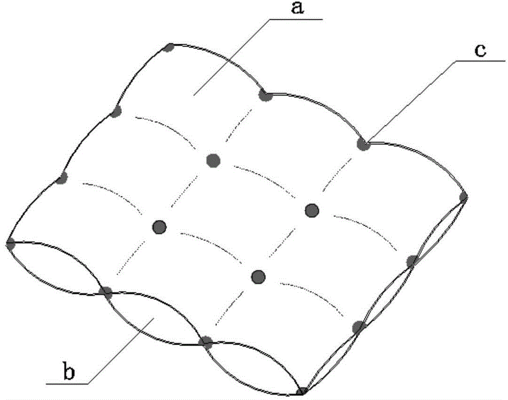
[0061] Such as figure 2 As shown, a plate heat exchange reactor is composed of a reactor shell 13, a material distributor, and a plate heat exchange element; the reactor shell 13 includes a reaction material inlet 1 and a reaction product outlet 12. Two plate heat exchange elements are arranged up and down, and each plate heat exchange element is provided with a heat exchange medium inlet and a heat exchange medium outlet. Among them, the lower plate heat exchange element is provided with a heat exchange medium inlet 3 and a heat exchange medium outlet 9 , the material distributor is arranged at the top or bottom of the reactor according to the reaction properties, and the structure of the upper and lower plate heat exchange elements is the same, and the structure of the lower plate heat exchange element is used as an example to illustrate its specific structure: the plate heat exchange element Including heat exchange plate pair 6, heat exchange medium inlet and outlet coils ...

Embodiment 2

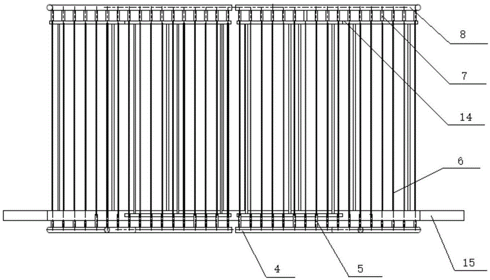
[0075] Such as Figure 5 As shown, the plate heat exchange element also includes a central air collecting pipe 18, and the distribution pipe includes an inner distribution cylinder 16 and an outer distribution cylinder 17, and the inner distribution cylinder 16 wraps around the central air collecting pipe 18 , the heat exchange plate pair 6 is arranged between the inner distribution cylinder 16 and the outer distribution cylinder 17, the heat exchange plate pair 6 is arranged perpendicular to the central gas collecting pipe, and many pairs of heat exchange plate pairs are evenly distributed in a radial shape On the inner distribution cylinder, an annular support member is provided at the bottom of the heat exchange plate pair 6 , and an annular heat exchange plate spacer 14 is provided at the top. The heat exchange plate pair 6 is composed of two metal flat plates passing through multiple solder joints, welded and stamped to form, and welded and sealed around it. Each heat exc...

Embodiment 3

[0078] Such as Figure 6 As shown, the plate heat exchange element also includes a central air collecting pipe 18, and the distribution pipe includes an inner distribution cylinder 16 and an outer distribution cylinder 17, and the inner distribution cylinder 16 wraps around the central air collecting pipe 18 , the heat exchange plate pair 6 is arranged between the inner distribution cylinder 16 and the outer distribution cylinder 17, the heat exchange plate pair 6 is arranged perpendicular to the central gas collecting pipe, and many pairs of heat exchange plate pairs are evenly distributed in a radial shape On the inner distribution cylinder, an annular support member is provided at the bottom of the heat exchange plate pair 6 , and an annular heat exchange plate spacer 14 is provided at the top. The heat exchange plate pair 6 is composed of two metal curved plates passing through multiple solder joints, welded and punched to form, and welded and sealed around it. Each heat e...


PUM


Abstract

The invention relates to a plate type heat exchange reactor which comprises a reactor shell, a material distributor and plate type heat exchange elements, wherein the reactor shell comprises at least one reaction material inlet and one reaction material outlet as well as at least one heat exchange medium inlet and one heat exchange medium outlet; the material distributor is arranged at the top or the bottom of the reactor according to the reaction property; each plate type heat exchange element comprises multiple heat exchange plate pairs, heat exchange medium inlet and outlet coil pipes and distribution pipes, two ends of each heat exchange plate pair are connected with the heat exchange medium inlet and outlet coil pipes through the distribution pipes, the heat exchange medium inlet and outlet coil pipes are connected with the heat exchange medium inlet and outlet, a plate-side pass cavity for medium circulation is formed in each heat exchange plate pair, and shell-side pass cavities for reaction material circulation are formed between adjacent heat exchange plate pairs as well as between each heat exchange plate pair and the reaction shell. Compared with the prior art, the plate type heat exchange reactor has the advantages of flexible structural adjustment, high heat exchange efficiency, low cost, convenience in cleaning and the like.

Description

technical field [0001] The invention relates to a plate heat exchange reactor, in particular to a novel high-efficiency plate heat exchange reactor. Background technique [0002] The thermal effect produced in the chemical reaction generally has a great influence on the reaction result, especially the strong exothermic and strong endothermic reactions, so heat exchange should be carried out while the reaction is in progress, so as to control the reaction well and get better results. result. At present, in the chemical industry, especially in the coal chemical industry, the scale of product equipment has a minimum limit and is getting larger and larger, so how to optimize and expand the heat exchange network in the reactor has become a key process factor. At present, in all kinds of reactors, the settings of the heat exchange system are generally classified according to the state of the reactant system. For example, in the gas-solid phase reaction, the catalyst in the fixed...

Claims


Application Information

Patent Timeline
Patent Type & Authority Applications(China)
IPC IPC(8): B01J8/02B01J8/00B01J19/00
Inventor 李凤清孙苑洱
Owner ATHCO ENG SHANGHAI CO LTD
Why Eureka
Try Eureka