
Navigation constellation inter-satellite link transceiver device time delay calibration method
A transceiver and inter-satellite link technology, which is used in satellite radio beacon positioning systems, measuring devices, instruments, etc., can solve the problem of inconsistent absolute delay values, inability to accurately characterize real-time delay values, and inappropriate equipment time. Delayed real-time, online accurate measurement and other issues
- Summary
- Abstract
- Description
- Claims
- Application Information
AI Technical Summary
Problems solved by technology
Method used
Image

Examples
Embodiment Construction
[0023] The present invention will be described in detail below with reference to the accompanying drawings and examples.
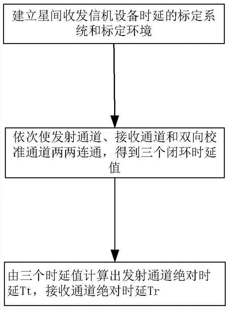
[0024] The present invention provides a method for calibrating the time delay of the transceiver equipment of the navigation constellation inter-satellite link, and the specific implementation steps are as follows figure 1 shown, including:
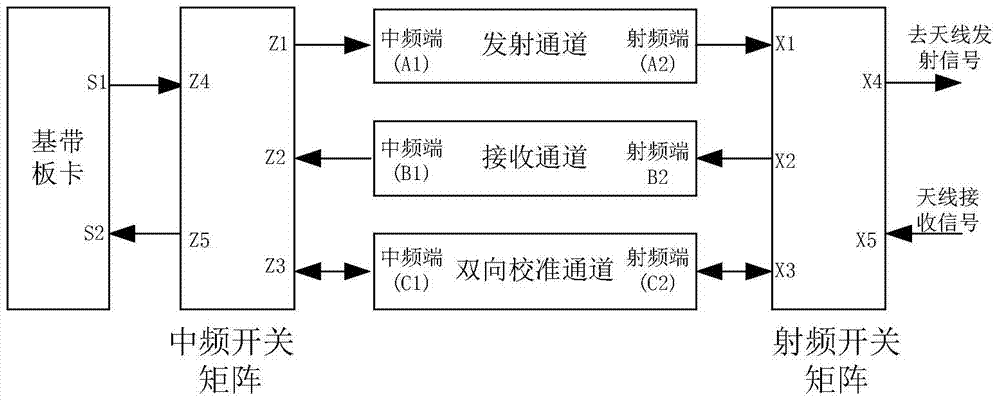
[0025] Step 1. Add a two-way calibration channel, an intermediate frequency switch matrix and a radio frequency switch matrix to the transceiver including the transmit channel, receive channel and baseband board to form a calibration system and calibration environment for the time delay of the transceiver equipment, so that the transmit channel, receive channels and bidirectional calibration channels are connected in parallel between the IF switch matrix and the RF switch matrix, and the baseband board is connected to the IF switch matrix, such as figure 2 shown.
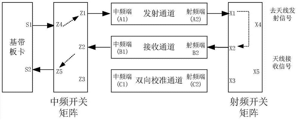
[0026] Step 2. Time-sharing control of the RF swit...
PUM
 Abstract
Description
Claims
Application Information