Design method of electro-permanent magnet rotor system based on rotor profile and magnetic field coupling

A magnetic field coupling, permanent magnet rotor technology, applied in computing, electrical digital data processing, special data processing applications, etc., can solve problems such as no explanation or report found, and data not yet collected.

Active Publication Date: 2017-09-08
SHANGHAI JIAO TONG UNIV
View PDF3 Cites 0 Cited by
  • Summary
  • Abstract
  • Description
  • Claims
  • Application Information

AI Technical Summary

Problems solved by technology

[0003] At present, there is no description or report of the similar technology of the present invention, and no similar data at home and abroad have been collected yet.

Method used


Image

  • Design method of electro-permanent magnet rotor system based on rotor profile and magnetic field coupling
  • Design method of electro-permanent magnet rotor system based on rotor profile and magnetic field coupling
  • Design method of electro-permanent magnet rotor system based on rotor profile and magnetic field coupling

Examples


Embodiment Construction

[0081] The following is a detailed description of the embodiments of the present invention: this embodiment is implemented on the premise of the technical solution of the present invention, and provides detailed implementation methods and specific operation processes. It should be noted that those skilled in the art can make several modifications and improvements without departing from the concept of the present invention, and these all belong to the protection scope of the present invention.

[0082] Please also see Figure 1 to Figure 10 .

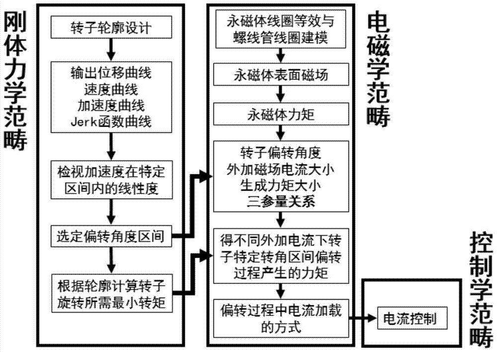
[0083] This embodiment provides an electro-permanent magnet rotor system design method based on rotor profile and magnetic field coupling, including the following steps:

[0084] Step 1, rotor profile design, specifically includes the following steps:

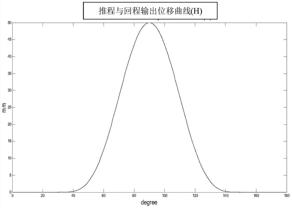
[0085] Step 1.1, use the double harmonic function to carry out the preliminary design of the rotor profile curve, as follows:

[0086] H(θ)=A 1 cos(πθ)+A 2 cos(2πθ)+K (1)
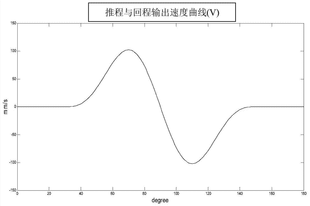
[0087] v...


PUM


Abstract

The invention provides a rotor profile type and magnetic field coupling based electric and permanent magnet rotor system design method. The rotor profile type and magnetic field coupling based electric and permanent magnet rotor system design method comprises the following steps of step 1, the rotor profile design; step 2, the magnetic field coupling rapid algorithm; step 3, the control method design of a driving mechanism. The rotor profile type and magnetic field coupling based electric and permanent magnet rotor system design method is a complete design scheme for an electric and permanent magnet rotor direct driving system, the initial rotor profile extends to the magnetic field calculation, and the feasible method for controlling the driving system is provided finally. According to the driving system design achieved by the rotor profile type and magnetic field coupling based electric and permanent magnet rotor system design method, the displacement, speed and acceleration output of the system can be directly determined through the control of the current and the annular current coil based permanent magnet magnetic field calculation mode is provided for the electromagnetism calculation and accordingly the multivariate solving can be rapidly performed in comparison with other electromagnetism commercial calculator software and the invested time cost required by the early design is greatly reduced.

Description

technical field [0001] The present invention relates to the technical field of auxiliary design process of an electromagnetic-permanent magnet coupling drive system, in particular to an electro-permanent magnet rotor system design method based on rotor profile and magnetic field coupling. Background technique [0002] In the electric-permanent magnetic coupling direct drive, the profile of the permanent magnet rotor directly affects the output performance of the drive, so it is necessary to develop a set of procedures for designing the rotor profile to meet the specific output requirements of the drive. In addition, since the rotor is driven by the coupling of the permanent magnet magnetic field and the external electromagnetic field to generate torque, the result of the magnetic field coupling must be calculated. However, the calculation results cannot be quickly obtained by using general commercial large-scale electromagnetic calculation software, and the long solution tim...

Claims


Application Information

Patent Timeline
Patent Type & Authority Patents(China)
IPC IPC(8): G06F17/50
Inventor 廖淳凯杨斌堂
Owner SHANGHAI JIAO TONG UNIV
Why Eureka
Try Eureka