Eureka AIR delivers breakthrough ideas for toughest innovation challenges, trusted by R&D personnel around the world.

Electro-optic Q-switch pulse laser with controllable single-pulse beam splitting ratio

A pulsed laser, single-pulse technology, applied in the field of lasers, can solve the problems such as the inability to realize the control of the beam splitting ratio of a single electro-optical Q-switched laser pulse, and the inability of electro-optical Q-switched laser pulses

Active Publication Date: 2015-01-07
BEIJING INST OF OPTO-ELECTRONIC TECH
View PDF5 Cites 2 Cited by
  • Summary
  • Abstract
  • Description
  • Claims
  • Application Information

AI Technical Summary

Problems solved by technology

[0004] Electro-optic Q-switched lasers usually only output a laser beam containing several electro-optic Q-switched laser pulses. After using a beam splitter at the output end of the laser, two laser beams can be formed, but the beam splitting ratio of the two laser beams is fixed. Adjusting the beam splitter can adjust the beam splitting ratio of the two laser beams, but this adjustment is to adjust multiple electro-optic Q-switched laser pulses in the laser beam together, not for the specified electro-optic Q-switched laser pulse, let alone Controlling the splitting ratio of a single electro-optic Q-switched laser pulse

Method used


Image

  • Electro-optic Q-switch pulse laser with controllable single-pulse beam splitting ratio
  • Electro-optic Q-switch pulse laser with controllable single-pulse beam splitting ratio
  • Electro-optic Q-switch pulse laser with controllable single-pulse beam splitting ratio

Examples


Embodiment Construction

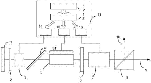
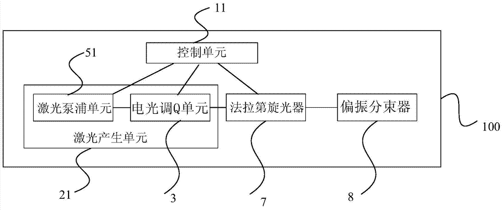
[0025] figure 1 A structural block diagram of an electro-optic Q-switched pulse laser with a single pulse splitting ratio controllable provided for the embodiment of the present invention. Such as figure 1 As shown, the single pulse splitting ratio controllable electro-optic Q-switched pulsed laser 100 includes a laser generating unit 21, a Faraday rotator 7, a polarization beam splitter 8 and a control unit 11, wherein the laser generating unit 21 generates electro-optic Q-switched laser pulses; The Faraday rotator 7 rotates the polarization direction of the electro-optic Q-switched laser pulse; the polarization beam splitter 8 divides the electro-optic Q-switched laser pulse into a first laser pulse and a second laser pulse; the laser pump in the control unit 11 and the laser generating unit 21 The pumping unit 51, the electro-optic Q-switching unit 3 and the Faraday rotator 7 are electrically connected, and the control unit 11 controls the working states of the laser pumpi...


PUM


Abstract

The invention provides an electro-optic Q-switch pulse laser with the controllable single-pulse beam splitting ratio. The electro-optic Q-switch pulse laser comprises a laser generating unit, a Faraday activizer, a polarization beam splitter and a control unit. The laser generating unit generates electro-optic Q-switch laser pulses. The polarization directions of the electro-optic Q-switch laser pulses are rotated through the Faraday activizer. The electro-optic Q-switch laser pulses are split by the polarization beam splitter into first laser pulses and second laser pulses. The control unit is electrically connected with a laser pumping unit and an electro-optic Q-switch unit in the laser generating unit and the Faraday activizer. According to the electro-optic Q-switch pulse laser, the polarization directions of the electro-optic Q-switch laser pulses are rotated by different angles through the Faraday activizer according to the preset beam splitting ratio so that the included angles between the polarization directions of the electro-optic Q-switch laser pulses and the polarization transmitting direction of the polarization beam splitter can be changed, the beam splitting ratio of the first laser pulses to the second laser pulses formed by splitting the electro-optic Q-switch laser pulses is adjusted, and the beam splitting ratio of the single electro-optic Q-switch laser pulses is controlled.

Description

technical field [0001] The invention relates to laser technology, in particular to an electro-optic Q-switched pulse laser with controllable single pulse splitting ratio. Background technique [0002] Q-switched laser technology is an important technology that compresses all the energy of the laser into a very narrow pulse and emits it, thereby increasing the peak power of the laser by several orders of magnitude. Q-switched switching devices with short switching times (about 10 -9 s), high efficiency, precise control of Q-switching time, narrow output pulse width (10-20ns), high peak power (above tens of MW), etc., is a widely used Q-switching technology at present. [0003] An electro-optic Q-switched laser is usually composed of a total reflection mirror, a λ / 4 wave plate, an electro-optic Q-switched crystal, a polarizer, a laser gain medium, and an output mirror. In the state of energy storage, when the voltage is applied to the Q-switching crystal, the laser outputs e...

Claims


Application Information

Patent Timeline
IPC IPC(8): H01S3/115
Inventor 王涛张玉莹陆耀东张强徐磊陈彬彬任奕奕
Owner BEIJING INST OF OPTO-ELECTRONIC TECH
Why Eureka
Eureka Blog
Learn More