
Compensation device for distributed series capacitor

A series capacitor and compensation device technology, applied in circuit devices, reactive power compensation, reactive power adjustment/elimination/compensation, etc. Layout, simple function, cost reduction effect

Active Publication Date: 2015-01-07
STATE GRID CORP OF CHINA +1
View PDF5 Cites 7 Cited by
  • Summary
  • Abstract
  • Description
  • Claims
  • Application Information

AI Technical Summary

Problems solved by technology

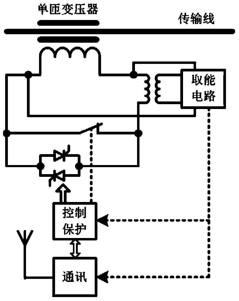
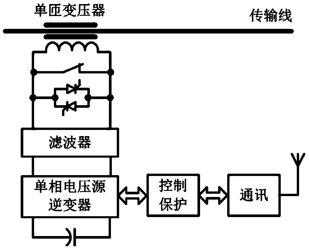
Obviously, if Figure 4 The typical main circuit structure of the EHV and UHV fixed series compensation shown cannot be used as the main circuit structure of the distributed series capacitor compensation device.

Method used


Image

  • Compensation device for distributed series capacitor
  • Compensation device for distributed series capacitor
  • Compensation device for distributed series capacitor

Examples


Embodiment Construction

[0067] The specific embodiments of the present invention will be further described in detail below in conjunction with the accompanying drawings.

[0068] Such as Figure 5 as shown, Figure 5 It is a schematic diagram of the main circuit structure of the distributed series capacitor compensation device in the present invention; the primary part of the distributed series capacitor compensation device provided by the present invention includes a normally closed bypass circuit breaker 9, a series capacitor 10, a thyristor 11, and a damping device 12.

[0069] The thyristor 11 and the damping device 12 are connected in series, and the series connected thyristor 11 and the damping device 12 , the bypass circuit breaker 9 and the series capacitor 10 are connected in parallel.

[0070] The normally closed bypass circuit breaker 9 can be an air circuit breaker or an air switch. The following requirements must be met:

[0071] 1. It can break the corresponding load current of the l...


PUM


Abstract

The invention provides a compensation device for a distributed series capacitor. The primary part of the compensation device comprises a bypass breaker, the series capacitor and a thyristor damping branch, wherein the bypass breaker, the series capacitor and the thyristor damping branch are connected in parallel. The thyristor damping branch comprises a thyristor and a damping device which are connected in series. A control and protection system of the compensation device comprises a control module, a protection module and a communication module. The compensation device is provided with few sub equipment, the weight and cost of the whole device are controlled efficiently, and main wiring of the compensation device is greatly simplified on the premise of reducing the cost of a whole set of series compensation device, so that the reliability of the whole compensation device is improved.

Description

technical field [0001] The invention relates to a device in the technical field of series capacitor compensation, in particular to a distributed series capacitor compensation device. Background technique [0002] Flexible alternative current transmission systems (FACTS) is an AC transmission technology that implements flexible and fast adjustment of the impedance, voltage, phase, power, etc. of the AC transmission system based on power electronics technology and control technology; it can be used to adjust the active power of the system Flexible control with reactive power flow to achieve the purpose of improving line transmission capacity, damping system oscillation, improving system stability, improving power quality, and improving reliability. FACTS technology has changed the concept of traditional AC transmission and brought about major changes in the modern power system. [0003] The large-scale FACTS device has powerful functions, complex structure, large floor area, ...

Claims


Application Information

Patent Timeline
Patent Type & Authority Applications(China)
IPC IPC(8): H02J3/18H02J13/00
CPCH02J3/1807H02J13/0017Y02E40/30Y02E40/70Y04S10/22
Inventor 戴朝波
Owner STATE GRID CORP OF CHINA
Learn More