Resistance changing structure for electro-hydraulic starter rheostat

A starter and electro-hydraulic technology, applied in the direction of liquid resistors, electric/electric converters, starter parts, etc., can solve the problems of low efficiency of high current, rust of mechanical structure, and great waste of electric energy, etc., to achieve maintenance The effect of extending the cycle, preventing water loss, and easy and convenient maintenance

Active Publication Date: 2015-01-07
南通曼淇威电气有限公司
View PDF6 Cites 1 Cited by
  • Summary
  • Abstract
  • Description
  • Claims
  • Application Information

AI Technical Summary

Problems solved by technology

[0003] The electro-hydraulic rheostat starter is used to start the motor. We know that when the motor starts, the starting current is very large. At this time, the efficiency of the large current is very low. Therefore, the waste of electric energy is very large. In order to solve this technical problem, a common solution One is to connect rheostats in series to limit the current, gradually increase the speed of the motor through the rheostats, and finally achieve the goal of energy saving. variable resistance
In the existing technology, water is easy to evaporate, and the mechanical structure is easily affected by water vapor to rust. As the water level drops, it is necessary to continuously add water

Method used


Image

  • Resistance changing structure for electro-hydraulic starter rheostat
  • Resistance changing structure for electro-hydraulic starter rheostat
  • Resistance changing structure for electro-hydraulic starter rheostat

Examples


Embodiment Construction

[0042] Now in conjunction with accompanying drawing, the present invention will be further described:

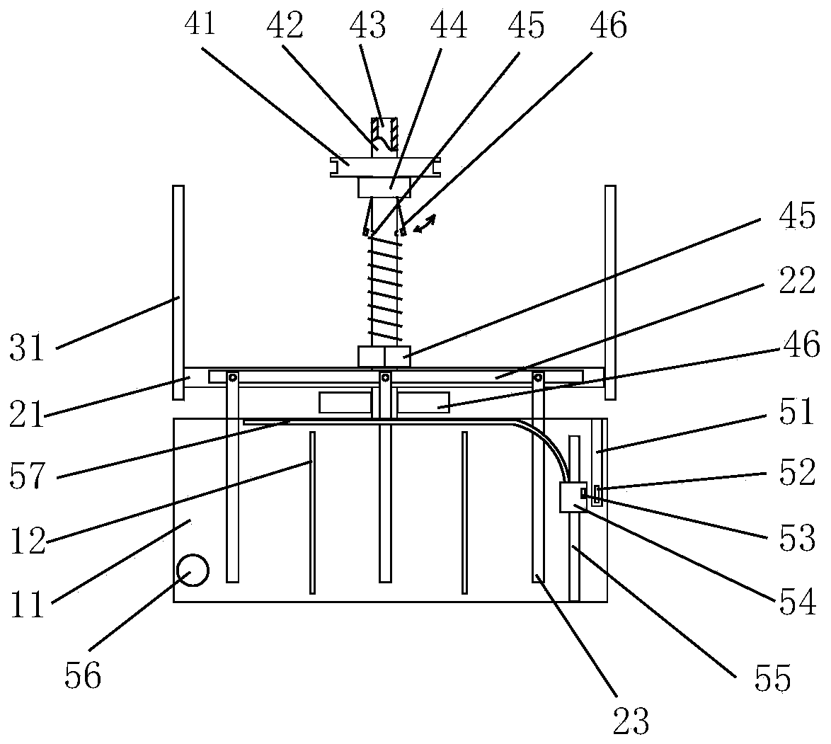
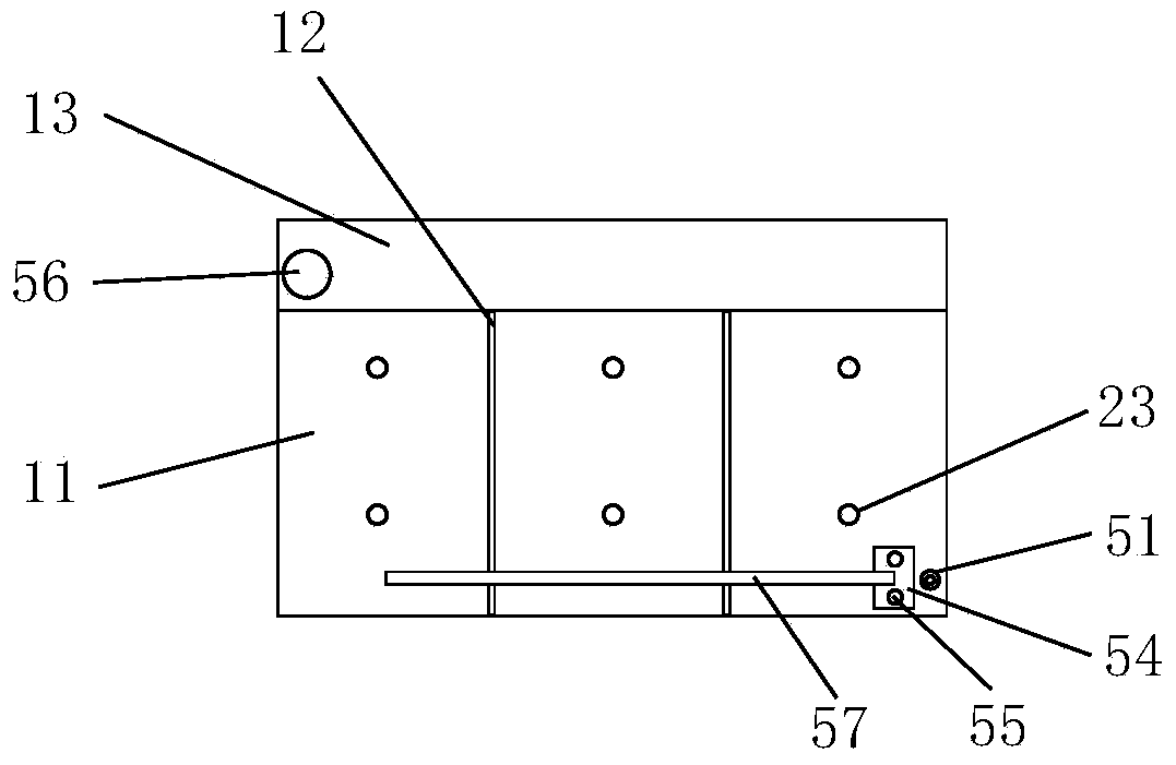
[0043] As shown in the figure, the water tank 11 is used as a water resistance;

[0044] Three pairs of electrode rods 23 are connected to water resistors and can output three resistance values;

[0045] The electrode rod lifting structure can simultaneously control the movement of one of each pair of electrode rods 23, thereby changing the water resistance;

[0046] The electrode rod lifting structure includes:

[0047] Screw rod 42, two ends are respectively fixed on the frame by upper bearing 44 and lower bearing 46;

[0048] Nut 45 cooperates with screw rod 42;

[0049] Insulation frame 21 is fixed with nut 45;

[0050] An electrode plate 22 is fixed to one of each pair of electrode rods 23;

[0051] Another one of every pair of electrode rods 23 is fixed on the frame by an insulating plate;

[0052] Guide rail 31, is provided with two, is fixed on the frame, can e...


PUM


Abstract

The invention discloses a resistance changing structure for an electro-hydraulic starter rheostat. The resistance changing structure for the electro-hydraulic starter rheostat comprises a water tank, three pairs of electrode bars and an electrode bar lifting structure. The electrode bar lifting structure comprises a screw rod, a nut and a belt pulley, wherein the nut is matched with the screw rod, and the belt pulley is mounted on the screw rod and is in linkage with a motor. The motor rotates and drives one of each pair of electrode bars to move up and down. An oil cavity containing oil is formed in the top of the screw rod, and an oil hole communicated with the oil cavity is formed in the upper portion of the screw rod. The resistance changing structure for the electro-hydraulic starter rheostat further comprises an oscillating rod, one end of the oscillating rod is hinged to the screw rod, and a sealing block is arranged at the other end of the oscillating rod. The oscillating rod falls naturally under the action of gravity. The sealing block can seal the oil hole. When the screw rod rotates, the oscillating rod opens the oil hole under the action of centrifugal force for releasing oil, and the screw rod and the nut are lubricated. The resistance changing structure for the electro-hydraulic starter rheostat further comprises a standby water tank, an automatic water charging system and a sealing system preventing water from losing. The resistance changing structure for the electro-hydraulic starter rheostat has the advantages that lubricating oil is added automatically through a rotating mechanism, water is added automatically, water loss is prevented, maintenance is easy and convenient to carry out, and a maintenance period is prolonged.

Description

technical field [0001] The invention relates to a rheostat structure of an electro-hydraulic rheostat starter, which belongs to the field of motor soft starting. [0002] Background technique [0003] The electro-hydraulic rheostat starter is used to start the motor. We know that when the motor starts, the starting current is very large. At this time, the efficiency of the large current is very low. Therefore, the waste of electric energy is very large. In order to solve this technical problem, a common solution One is to connect rheostats in series to limit the current, gradually increase the speed of the motor through the rheostats, and finally achieve the goal of energy saving. variable resistance. In the prior art, water is easy to evaporate, and the mechanical structure is easily affected by water vapor to rust. As the water level drops, it is necessary to continuously add water. Contents of the invention [0004] Based on the above disadvantages, the present inven...

Claims


Application Information

Patent Timeline
Patent Type & Authority Applications(China)
IPC IPC(8): H02P1/02H01C10/02
CPCH01C10/02H02P1/027
Inventor 江永江加宝章春全
Owner 南通曼淇威电气有限公司
Why Eureka
Try Eureka