
Slurry ball valve

A slurry ball valve and sphere technology, which is applied to valve devices, cocks including cut-off devices, engine components, etc., can solve the problems of severe sealing surface erosion, short service life of valves, and reduced service life of valves, achieving reliable sealing performance, The valve opens and closes quickly and reduces the effect of operating torque

Inactive Publication Date: 2015-01-14
SICHUAN KAITZ VALVE MFG
View PDF3 Cites 1 Cited by
  • Summary
  • Abstract
  • Description
  • Claims
  • Application Information

AI Technical Summary

Problems solved by technology

The pre-tightening spring of the existing slurry ball valve generally adopts a helical spring. Because the conveying medium is solid particles, the particles will gather in the spring hole during the use of the valve, causing the spring to be stuck and the valve seal to fail immediately.
[0003] Moreover, due to the high flow rate and high hardness of the conveying medium, the erosion of the sealing surface by the medium is very serious. The sealing surface of ordinary hard-sealed ball valves will be destroyed by the medium soon, and the service life of the valve is extremely short.
[0004] In addition, because the opening and closing frequency of the slurry ball valve is relatively fast, the opening and closing is usually completed in a few minutes. Frequent opening and closing will increase the wear of the ball and reduce the service life of the valve.

Method used


Image

  • Slurry ball valve
  • Slurry ball valve

Examples


Embodiment Construction

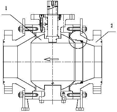
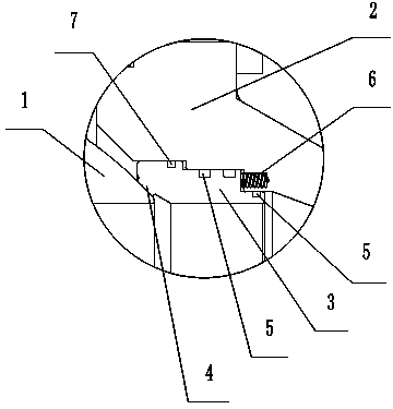
[0013] As an embodiment of the present invention, such as figure 1 and figure 2 As shown, a slurry ball valve includes a valve body, a sphere 1 and two bonnets 2 arranged on opposite sides of the sphere 1. The inner hole of the bonnet 2 near the end of the sphere 1 has a larger diameter than the end far away from the sphere 1. A valve seat support ring 3 is arranged between the upstream valve cover 2 and the sphere 1, a valve seat 4 is provided at one end of the valve seat support ring 3 close to the sphere 1, and the outer wall of the valve seat support ring 3 is stepped, The outer diameter of the end close to the sphere 1 is larger than the end far away from the sphere 1, and the two side wall surfaces with different outer diameters of the valve seat support ring 3 are respectively provided with O-shaped sealing rings 5 ​​along the circumferential direction to form two radial sealing surfaces, as a preferred The two side wall surfaces with different outer diameters of the ...


PUM


Abstract

The invention discloses a slurry ball valve and relates to a valve. The slurry ball valve comprises a valve body, a ball and two valve decks arranged on the two opposite sides of the ball. The hole diameters of the ends, close to the ball, of inner holes of the valve decks are larger than the hole diameters of the ends away from the ball, of the inner holes, a valve seat supporting ring is arranged between the valve deck located on the upstream and the ball, a valve seat is arranged at the end, close to the ball, of the valve seat supporting ring, the outer side wall of the valve seat supporting ring is in a stair shape, the outer diameter of the end, close to the ball, of the valve seat supporting ring is larger than the outer diameter of the end, away from the ball, of the valve seat supporting ring, O-shaped sealing rings are arranged on the surfaces of the two side walls, different in outer diameter, of the valve seat bearing ring respectively in the circumferential direction to form two radial sealing faces, a pre-tightening spring is arranged between the valve seat supporting ring and the corresponding valve deck, and the pre-tightening spring is arranged between the upper O-shaped sealing ring and the lower O-shaped sealing ring in the horizontal direction. The pre-tightening spring cannot be stuck by medium crystal substances, washing to the sealing faces by media can be overcome, the abrasion of the ball can be reduced, the service life of the valve can be prolonged, and high practicability is achieved.

Description

technical field [0001] The invention relates to a valve, in particular to a slurry ball valve. Background technique [0002] Slurry ball valves are mainly used in the coal mine industry and thermal power stations. The valves are installed on pipelines conveying high-velocity solid particles (such as coal ash, etc.) as opening and closing parts, and the valves are frequently opened and closed. The pre-tightening spring of the existing slurry ball valve generally adopts a coil spring. Since the conveying medium is solid particles, the particles will gather in the spring hole during the use of the valve, causing the spring to be stuck and the valve seal to fail immediately. [0003] Moreover, due to the high flow rate and high hardness of the conveying medium, the erosion of the sealing surface by the medium is very serious. The sealing surface of ordinary hard-sealed ball valves will be destroyed by the medium soon, and the service life of the valve is extremely short. [00...

Claims


Application Information

Patent Timeline
IPC IPC(8): F16K5/06F16K5/20
CPCF16K5/202F16K5/08
Inventor 吴建林郭滕毅
Owner SICHUAN KAITZ VALVE MFG
Learn More